This material has the appearance of metal.
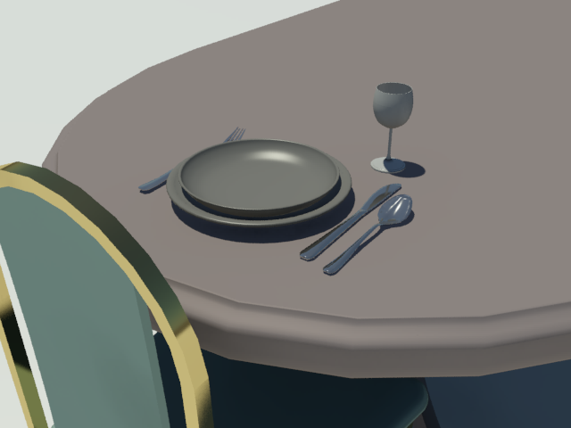
Autodesk Metal with a type of Stainless Steel applied to the utensils, and with a type of Brass applied to the framework of the chair
Interface
Metal rollout
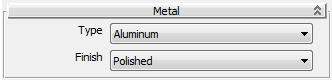
- Type
-
Sets the base color and texture of the material, and controls which properties are used.
- Aluminum (The default.) For Aluminum, you can change the Finish.
- Anodized Aluminum For Anodized Aluminum, you can change the Color.
- Chrome For Chrome, you can change the Finish.
- Copper For Copper, you can change the Patina and the Finish.
- Brass For Brass, you can change the Finish.
- Bronze For Bronze, you can change the Patina and the Finish.
- Stainless Steel For Stainless Steel, you can change the Finish.
- Zinc For Zinc, there are no further options.
- Color (appears only for Anodized Aluminum)
-
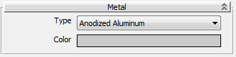
Lets you set a custom color for Anodized Aluminum.
- Patina (appears only for Copper and Bronze)
-
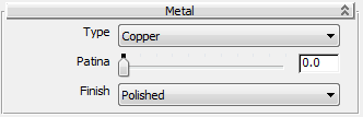
Lets you set a patina for Copper or Bronze. The higher the value, the more the amount of patina. Range: 0 to 1.0. Default=0.0.
- Finish (does not appear for Anodized Aluminum or Zinc)
-
Lets you set a surface finish for Aluminum, Chrome, Copper, Brass, Bronze, or Stainless Steel.
- Polished (The default.)
- Semi-polished
- Satin
- Brushed
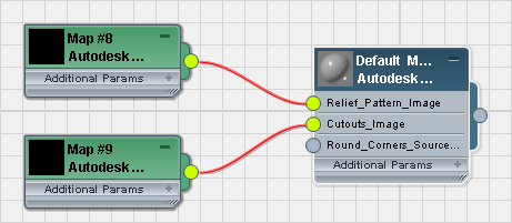
Relief Pattern rollout
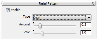
- Enable
-
When on, applies a relief pattern to the material. Default=off.
- Type
-
Lets you choose a predefined relief pattern, or create a custom pattern.
- Knurl (The default.)
- Diamond Plate
- Checker Plate
- Custom - Image Lets you choose a bitmap to control the relief pattern.
- Image (appears only for Custom - Image)
-
When Custom - Image is the active Type, click to specify a bitmap for the relief pattern.
- Amount
-
Controls the height of the relief. Range: 0.0 to 2.0. Default=0.3.
- Scale
-
Adjusts the scale of the relief pattern. Range: 0.0 to 5.0. Default=1.0.
Cutouts rollout
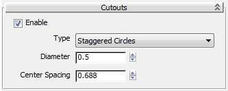
- Enable
-
When on, enables the use of Cutout maps for the material. Default=off
- Type
-
Lets you choose a predefined cutout pattern or create a custom pattern.
For the cutout patterns that let you adjust dimensions, the values are set in inches.
- Staggered Circles (The default.) For the Staggered Circles pattern, you can set a Diameter and a Center Spacing distance.
- Straight Circles For the Straight Circles pattern, you can set a Diameter and a Center Spacing distance.
- Squares For the Squares pattern, you can set a Size and a Center Spacing distance.
-
Grecian For the Grecian pattern, there are no additional settings.
The Grecian pattern is 0.625” square, and the squares are separated by 0.125”.
-
Cloverleaf For the Cloverleaf pattern, there are no additional settings.
The Cloverleaf height (at the waist of each lobe) is 0.25”, and the width (from the apex of one lobe to the apex of the opposite lobe) is 0.5”
-
Hexagon For the Hexagon pattern, there are no additional settings.
The Hexagon height (the long dimension) is 0.3125”, and the width (the narrow dimension) is 0.25”.
- Custom For the Custom pattern, the Image button lets you choose a map to generate cutouts. The default map type is Autodesk Bitmap, but you can choose a different type using standard Material Editor methods.