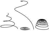
Use Helix to create open flat or 3D helices or spirals.

Examples of helices
Procedures
To create a helix:
- Go to the
 Create panel, click
 (Shapes), then click the Helix button.
Note: The default creation method, on the Creation Method rollout, is Center. This means that where you start creating the helix becomes its center point. Alternatively, you can start at the edge.
 - In any viewport, drag and release to set the starting point of the helix and its starting radius (Center method) or diameter (Edge method).
- Move the mouse vertically and then click to define the height.
If you create the helix in an orthographic viewport, such as Top or Front, you'll need to view the change in height in another viewport, such as Perspective.
- Move the mouse and then click to define the end radius.
Interface
Rendering rollout
Most spline-based shapes share these parameters. For details, see Rendering rollout.
Creation Method rollout
The Helix shape offers the standard creation-method choice: Center or Edge. For an explanation, see Creation Method rollout.
Keyboard Entry rollout
Creates a Helix spline from the keyboard. Use the X/Y/Z settings to specify the center point, and the remaining parameters to specify the radii and height, then click Create. After creating the spline, you can use the Parameters rollout controls to adjust its settings (see following).
Parameters rollout

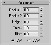
Once you have created a helix, you can make changes using the following parameters:
- Radius 1
-
Specifies the radius for the Helix start.
- Radius 2
-
Specifies the radius for the Helix end.
- Height
-
Specifies the height of the Helix.
- Turns
-
Specifies the number of turns the Helix makes between its start and end points.
- Bias
-
Forces the turns to accumulate at one end of the helix. Bias has no visible affect when the height is 0.0.

Helical spline varied only by bias settings
- A bias of –1.0 forces the turns toward the start of the helix.
- A bias of 0.0 evenly distributes the turns between the ends.
- A bias of 1.0 forces the turns toward the end of the helix.
- CW/CCW
-
The direction buttons set whether the Helix turns clockwise (CW) or counterclockwise (CCW).
Converting Helices into Meshes
The conversion of a shape to a mesh uses the capping mechanism on closed shapes to create a solid mesh shape. With an open shape such as a helix, the capping cannot be performed, resulting in an usable mesh with vertices but no faces.
To properly convert a helix into a mesh, first open the Rendering rollout for the shape and check Enable in Viewport. Next, set the desired parameters for the shape's thickness. When the shape is then converted, a usable mesh will result.