Model views are local areas from the 3D model that display only objects within the defined space.
When constructing a large model with many elements, an isometric view can be confusing. You can use model views to limit the number of displayed elements and display just the relevant objects in the right area. For example, you can display only one frame in 2D view.
There are different types of saved views:
- Free defined views.
- Levels.
Different view directions can be selected during the model view creation.
Define the Box and the View Direction
The Model view tool ( ) defines the box and view direction using the following methods:

|
By specifying one point in the current UCS. | The model view is centered about a selected point. |
|
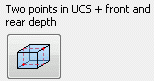
By two points in the current UCS and the front and rear depth. | |

|
At a grid line. | The model view is created based on one of the grid lines. The length of the grid line defines the width of the view. The height of the view is unlimited. |

|
At a joint box. | The model view is created based on the connection object (box) of a joint (standard joint, user joint or structural element). |
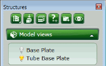
The created model views are listed in the Project Explorer.
Use the Model Views
Saved model views are a cosmetic tool used to reduce data on screen, improving clarity and performance.
You can turn a model view on or off using the light bulb in front of the view name. Only the objects within the defined box are displayed. Objects partially in the defined box are clipped.
- Turning on several model views will display all elements within the boundaries of all the views combined and not several isolated areas.
- Hidden elements can still be selected using the Search filter.
Edit the Model Views
Saved model views can be modified.
- Change the name of a model view.
- Change the size of a model view.
- Modify the properties.