Learn how to define cladding areas and opening for roofs and walls.
Define the Cladding Area
Using this tool you can define the supporting elements and the covering area.
Access the command
In the Extended Modeling tab  Structural Elements panel, click
 (Define cladding area).
Command line: _AstM4CreateArea
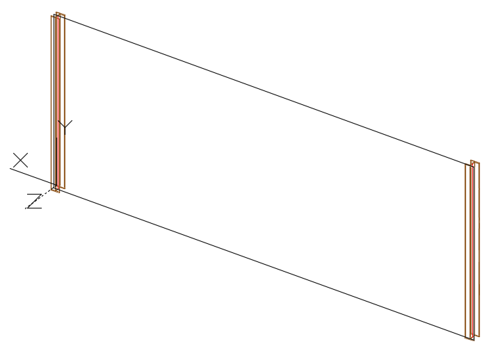
Define a rectangular cladding area
- Place a coordinate system with the X/Y plane in the required covering area plane.
- In the Extended Modeling tab Structural Elements panel, click
(Define cladding area).
- Select the beam and press Enter.
- On the command line, Type R (Rectangular) and press Enter.
- Input the two diagonally opposite points defining the rectangular cladding area.
- The area is created.
Define Area Openings
Using this tool you can define openings in the covering area. This object stores the information about the opening type (window, door) and is used at the cladding system creation.
Access the command
In the Extended Modeling tab Structural Elements panel, click
 (Define cladding opening).
Command line: _AstM4CreateOpening
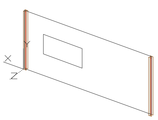
Define a rectangular opening in the cladding area
- In the Extended Modeling tab Structural Elements panel, click
(Define cladding opening).
- On the command line, type R (Rectangular) and press Enter.
- Select the cladding area object.
- Input the two diagonally opposite points defining the rectangular opening.
- The opening is created.
Insert Claddings
Using this tool you can insert a single cladding panel in the selected area.
Access the command
In the Extended Modeling tab Structural Elements panel, click
 (Create claddings).
Command line: _AstM4CrConByVB CreateCladding
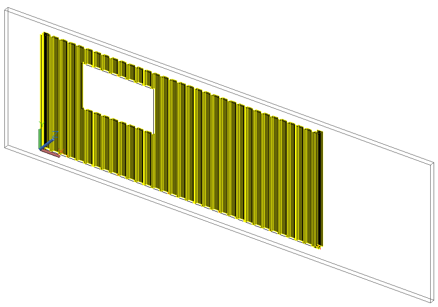
Insert claddings in a rectangular area, with an opening
- In the Extended Modeling tab Structural Elements panel, click
(Create claddings).
- On the command line, type R (Rectangular) and press Enter.
- Select the cladding area object and press Enter.
- The cladding is created and the properties dialog box appears.