Learn how to create and use model views to better control the display of your 3D model.
Access the command
In the Quick views tool palette,
 (Create model views).
Command line: _AstM11CommCreateModelView
Define a model view by selecting one point in the UCS
- Place the UCS in a suitable position. The model view will display the XY plane.
- In the Quick views tool palette,
(Create model views).
- In the dialog box, select
 .
.
- Select a point that you wish to be the center of the model view area.
- On the command line, enter the view name and press Enter.
- A default view box appears and the arrows for defining the default view direction.
- Select one of the displayed arrows to define the view direction and press Enter.
- The model view is created and appears in the Project Explorer.
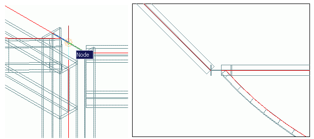
Example:
You can create a model view to display the intersection of elements. It is useful to more easily create the necessary connections. The default view direction is top view.
Define a model view by two points
- Select a suitable UCS.
- In the Quick views tool palette,
(Create model views).
- In the dialog box, select
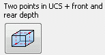 .
.
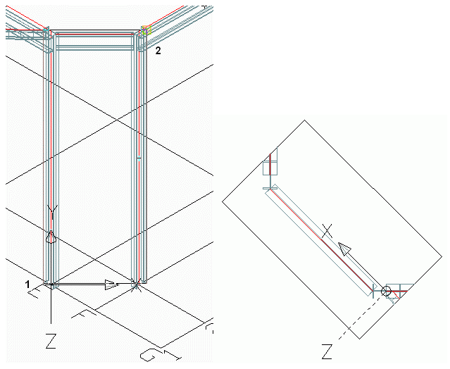
- Select two diagonal points in the view plane.
- On the command line, enter the front depth and press Enter.
- On the command line, enter the rear depth and press Enter.
- Enter the view name and press Enter.
- A default view box appears with arrows to define the view direction.
- Select one of the displayed arrows to define the view direction and press Enter.
- The model view is created and appears in the Project Explorer.
Example:
Define a model view at grid line
- In the Quick views tool palette,
(Create model views).
- In the dialog box, select
 .
.
- Select a grid line and press Enter.
- Enter the view name and press Enter.
- Select one of the displayed arrows to define the view direction and press Enter.
- The model view is created.
Example:
Define a model view at a joint box
- In the Quick views tool palette,
(Create model views).
- In the dialog box, select
 .
.
- Select the joint box and press Enter.
- On the command line, enter the view name and press Enter.
- Select one of the displayed arrows to define the view direction and press Enter.
- The model view is created.
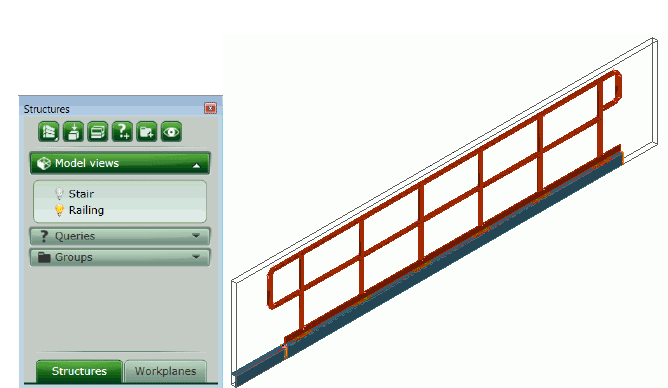
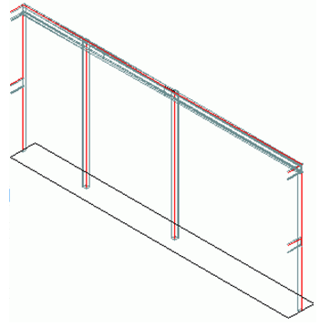
Example: Model view for a railing