This tool is useful for placement on existing objects. The position and orientation of the coordinate system corresponds to the coordinate system of the object at creation time. Thus, other objects with identical position and orientation can be created.
| Object | UCS origin location |
|---|---|
| Rectangular plates | In the center of the reference plane (zero position of the thickness). |
| Polygonal plates | In the corner corresponding to the first definition point. |
| Beams | At the beginning of the beam system line. This coordinate system has an orientation that allows the insertion of a new beam in the same orientation. |
To access the command
UCS tool palette:
 (Define coordinate system).
Command line: _AstM4CommShowLocalsCS
To define a UCS at an object
- UCS tool palette: Click
(Define coordinate system).
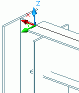
- Select the desired object, for example, a curved beam. At the end of the beam a red coordinate system appears. The longest line is in the Z-direction.
- Select a red coordinate system line and along with it, a coordinate system.
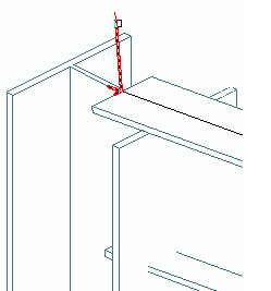
- Press <Enter> to confirm.
- The coordinate system is defined.