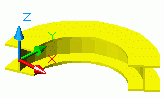
Curved beams are created in the Advance 3D model relative to the current user coordinate system (UCS) by entering three points that define an arc.
Like straight beams, the current coordinate system determines the position of the main axes of the beam. The curved beam web runs in the Z direction of the current UCS (the top of the section is in the Z direction). The created curved beam can be rotated by 90° about its system line.
Access the command
On the Objects tab  Beams panel, click
 (Curved beam).
Command line: _Astm4CommCrBeamBent
Create a curved beam using three points
- Select a suitable UCS.
- On the Objects tab Beams panel, click
(Curved beam).
- Specify the start point of the beam.
- Specify the end point of the beam.
- Click a circle point to define the radius of the curved beam. Make sure to define the circle point in the X/Y plane of the coordinate system.
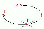
- The curved beam is created.
Modify the curved beam radius
- Select the curved beam.
- Right-click and select Advance Properties from the context menu.
- In the properties dialog box, go to the Positioning tab.
- In the Radius field enter the radius value.
Note: It is very important to set the required radius while the system line is at the center point (center of gravity). The system line can then be set to an edge and the radius previously entered will then correspond to that edge. The radius value in the dialog box changes since it displays the radius to the section center.