Export Active As
![]()
Allows you to translate Alias data into appropriate CAD file formats.
To save the entire scene (not just the picked objects), use File > Save or File > Save As
The window displays different options based on the file format you choose. Some file formats, such as OpenInventor, have no options.
Parasolid options
Logfile Output
Creates a report containing a list of path names of exported files, a list of warnings and/or error messages, a detailed entity mapping report and a table that documents the number of each type of entity processed during the import.
File Version
Choose which version of the file format you want to use.
Convert
NURBS Surfaces and Shells
Converts NURBS geometry (curves, surfaces, shells).
Curves
Converts curves.
Instances
Converts instanced geometry.
Symmetry
Converts layers with active symmetry. This is on by default.
Convert Invisible
Converts invisible geometry. This is on by default.
Keep Topology
Keeps topology for sheets and solids.
Split Periodic Surfaces
Divides closed/periodic surfaces into multiple surfaces. This is off by default.
Repair Options
JT options
AlToJt is a command-line utility which you can use to translate a wire file to JT format from the Command Prompt window, without running Alias. Type AlToJt -h to see a list of all available options and their definitions.
Below is a description of all the options in the option window, as well as their command-line equivalent.
Organize Data First By
This option allows you to organize your data by GEOMETRY, SHADER, LAYER or SBD structure type.
GEOMETRY – One DirectModel node object (.jt file) is generated for each geometry object. There is a one to one correspondence between a geometry object and its DirectModel part.
Command-line equivalent: -e1g
SHADER – One DirectModel node object (.jt file) is generated for each Alias shader.
Command-line equivalent: -e1s
LAYER – One DirectModel node object (.jt file) is generated for each Alias layer.
Command-line equivalent: -e1l
SBD Structure – The SBD structure in Alias is first translated to an assembly structure in DirectModel, then one DirectModel node object (.jt file) is generated for each geometry object.
Command-line equivalent: -e1b
Organize Data Second By
This option allows you to organize your data in a multi-level hierarchy structure. Organize Data First By creates the first hierarchy level, and Organize Data Second By lets you control how the second level of the hierarchy is constructed. This option is only available when Organize Data First By is set to SBD Structure, SHADER or LAYER. The following table shows the possible combinations:
| Organize Data First By | Organize Data Second By |
| Geometry | None |
| Shader | Layer / None |
| Layer | Shader / None |
| SBD Structure | Layer / Shader/ None |
Command-line equivalent: -e2b for SHADER and -e2l for LAYER.
Sort by Name
This option allows you to organize your geometry data (bottom level of the hierarchy) alphabetically by name.
It is only available when Organize Data First By is set to SHADER, or when it is set to SBD Structure and Organize Data Second By is SHADER or LAYER.
Create a Single File
This is turned on by default, so that wire files are converted into an assembly file and a folder containing a single file per part.
Command-line equivalent: -g to turn the option on.
Export Curves
This option is turned off by default so that 3D curves and curves on surface are not exported.
Command-line equivalent: -wc
Export Invisible data
This option is turned off by default so that invisible geometry is not exported.
Command-line equivalent: -wi
Export Templated data
This option is turned off by default so that templated geometry is not exported.
Command-line equivalent: -wt
Export Lights
This option is turned on by default so that all light information is exported. This forces the translator to process Alias lights.
If a light is assigned a name in Alias, the name will be exported as well.
Command-line equivalent: -xl
Export Shaders
This option is turned on by default so that all shader information is exported. When turned off, the translator ignores shader information.
If a shader is assigned a name in Alias, the name will be exported as well.
Command-line equivalent: -xs
Export Textures
This option is turned on by default so that all the texture information is exported. When turned off, the translator ignores texture information.
If a texture is assigned a name in Alias, the name will be exported as well.
Command-line equivalent: -xt
Export Symmetry
This option applies to layers that have mirror symmetry turned on in Alias.
Off: The instanced geometry is not exported. This is the default.
Merged: The instanced geometry is duplicated as additional geometry through the JT translator (AlToJt). Each instance is merged into the same node as its original geometry in the JT viewer program.
Command-line equivalent: -ws
Unmerged: The instanced geometry is duplicated as additional geometry through the JT translator (AlToJt), but the original and instanced geometry are located in separate nodes in the JT viewer program.
Command-line equivalent: -wsu
The Unmerged setting can be over-ridden on a per layer basis based on the layer name. If the layer name ends with -jtmrg, and symmetry is on for that layer, then geometry in that layer will be exported as if Export Symmetry was set to Merged.
Create Logfile
This option is turned on by default so that a log file is generated. The log file contains the time of the conversion, and the names and types of converted objects.
Command-line equivalent: -l
Stitch Surfaces
This option is turned off by default. When turned on, the B-Rep faces are sewn together along shared edges within a single part. This eliminates some problems with gaps between surfaces. However, this does not sew edges between two adjacent parts, but only between surfaces within a single part.
Command-line equivalent: -q to turn the option on.
Scale Factor
The default value is 1.0. 0.5 reduces the size by half; 2.0 makes it twice as large. This allows you to manipulate the scale on export.
Command-line equivalent: -s
Texture Image Resolution
The default is 128. This specifies texture file image resolution and is used during 3D (Solid or Environment) texture conversions. Valid resolutions are 8 to 8192.
Command-line equivalent: -u
Geometry Type
Choose Polygon to export only the polygons or Polygon + Brep to export the Brep representation as well.
Brep Type
This option only appears if Geometry Type is set to Polygon + Brep.
Choose XT Brep to create parasolid Brep data. You can also select JT Brep.
Tessellation Options
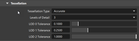
Tessellation Type
You can choose between three different tessellators:
Fast – Uses the same tessellator as Hardware Shade with the Fast option selected. This is the default. Command-line equivalent: -to.
Accurate – Uses the same tessellator as Hardware Shade with the Accurate option selected. Command-line equivalent: -ta. (This replaces the old AG tessellator.)
Current – This should give you the same tessellation as in Hardware Shade when Show Triangles is on (this option appears when Quality is set to User defined). Command-line equivalent: -td.
Levels of Detail
This option applies to Fast and Accurate tessellation modes only. It indicates the number of tessellations that will be saved in the JT file (1, 2, or 3). The default is 1.
LOD 0 tol
Use this slider to set the tessellation tolerance for the first tessellation. The default is 1.0
LOD 1 tol
This slider only appears if Levels of Detail is set to 2 or 3. Use it to set the tessellation tolerance for the second tessellation. The default is 2.5.
LOD 2 tol
This slider only appears if Levels of Detail is set to 3. Use it to set the tessellation tolerance for the third tessellation. The default is 10.0.
LOD labels
Labels can be assigned to the different LODs (tessellations) and appear in the option window next to the sliders.
Only the first 15 characters of the label names appear in the option window, although all are saved in the JT file. Allowed characters are letters (upper and lower case), numbers, underscore ("_") and white spaces.
Use one of the following methods to set labels:
Set these environment variables to the required names:
ALIAS_JT_LOD0_LABEL (first LOD)
ALIAS_JT_LOD1_LABEL (second LOD)
ALIAS_JT_LOD2_LABEL (third LOD)
For example: ALIAS_JT_LOD0_LABEL=Fine
Un-comment and set the following name-value pairs in the dt_jt.v.scm file (if you have administrator privileges):
 (ui-symbol "mo_eai_tess_lod0_label" "Fine")
 (ui-symbol "mo_eai_tess_lod1_label" "Medium")
 (ui-symbol "mo_eai_tess_lod2_label" "Coarse")
This file is found under the Alias installation in ALIAS_LOCATION\Scheme\Modeling where ALIAS_LOCATION is typically Program Files\Autodesk\Alias2023.
Note: Labels specified through the scheme file override the environment variables.
Related page
NX options
Output Units
Export in inches or millimeters.
File Version
Choose which version of the file format you want to use.
Convert
Meshes
Converts meshes to Facet entities.
Points
Converts Alias points/locators.
Nurbs
Converts NURBS geometry (curves, surfaces, shells).
Curves
Converts curves.
Template
Translates Alias template geometry (visible but not active geometry) to an NX prt file.
Keep Group Structure
Preserves the group structure of the source WIRE file. To be grouped in the resulting NX file, a member must be part of a group in the source WIRE file.
Symmetry Layer
Translates layers with active symmetry to an NX prt file.
Empty Layers
Translates empty layers. The Alias layers map directly to NX layers.
Empty Categories
Translates empty categories to an NX prt file. Alias categories map directly to NX categories. Layers are subsets of categories.
Layers to NX Categories
Maps layers to Categories.
Options
Logfile Output
Creates a report containing a list of path names of imported files, a list of warnings and/or error messages, a detailed entity mapping report and a table that documents the number of each type of entity processed during the import.
Simplify Primitives
Converts spline surfaces to analytic surfaces (cones, cylinders, spheres, tori). For example, a cylinder represented by a biquadratic NURBS surface in Alias will be converted to an analytic cylinder (defined by center, radius and axis) in NX.
Simplify Planes
Converts planar splines surfaces to analytic planes. For example, a plane defined using a bilinear NURBS surface in Alias will be converted into an analytic plane defined by a 3D point and normal in NX.
Split Periodic Surfaces
Divides periodic surfaces into multiple surfaces.
Color Definition File
Uses the specified .cdf (Siemens NX color definition file) file for configuring shader/material colors.
Before you create the model in Alias
- Set units to mm.
- In the Construction Settings window, toggle the Rational geometry flag toOFF.
Set tolerances as follows:
- Curve Fit Distance = .01 mm (lower as necessary)
- Curve Fit Checkpoints = 10
- Max Gap Distance = .01 mm (this value should remain the same as Curve Fit Distance)
- Trim Curve Fit =.005 mm (lower as necessary)
About creating the model
- Use degree 5 curves and surfaces to achieve curvature continuity between surfaces and successful data transfer.
- Periodically transfer models from Alias to NX during construction to manage the quality of the model being created.
- Stitch the Alias model successfully before export, but also periodically stitch the geometry to ensure that the model meets all tolerance requirements.
- Avoid using Attach
 tool since this tool creates multiknots in Alias geometry.
 - Avoid using Skin
 between trimmed surface boundaries, since excessive amounts of data are created in the resulting surface. If Skin is used between trim boundaries, check the resulting surfaces for multiknots before export.
 - Use surface building tools such as Square
 and Rail Surface
  to ensure and control curvature continuity between surfaces.
Workflow
Before transferring geometry between Alias and NX, consider the purpose of the transfer to plan an appropriate workflow.
Two common workflows are:
- Geometry (describing mechanical components) is transferred from NX to Alias to be used as reference data for concept design surfacing, then the Alias surface model is transferred back to NX.
- An Alias model is transferred to NX, and both Alias and NX Databases are developed independently. Later, the modified Alias model is transferred again to NX, replacing the Alias geometry from the first transfer. In this scenario, all work done in NX on the first Alias model transfer will affect the new, modified geometry.
There are many variations on these two examples. Whatever the transfer scenario, carefully plan the transfer process, to ensure that the appropriate data is written out and is useful.
Related pages:
NX part and assembly format Reference Interpret NX log files
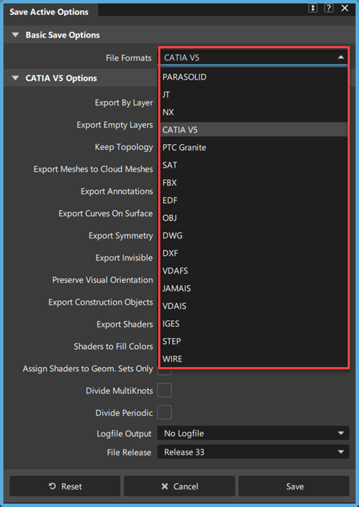
CATIA V5 options
Export By Layer
![]()
Convert layers to open body/geometrical sets (-a option specified for AlToC5). The default is on.
Export Empty Layers
The default is on.
Keep Topology
When this option is ON (default), Alias shells are converted to CATIA skins. When it is OFF (-s option specified for AlToC5), Alias shells are converted to CATIA Faces.
Export Meshes to Cloud Meshes
The default is on.
Export Curve on Surface
Curves-on-surface are converted to curves on export to CATIA V5. This option includes these curves in the CATIA V5 file. The default is ON (-x option specified for the AlToC5).
Export Symmetry
By default this option is OFF.
When ON (-b option specified for AlToC5), if an Alias layer has symmetry ON, this information is processed and the geometric objects resulting from the layer's symmetry are converted.
Export Invisible
By default this option is ON.
By default, Alias invisible geometric entities are converted to CATIA invisible (hidden) entities. When OFF (-v option specified for AlToC5), Alias invisible geometric entities are ignored and are not converted.
Preserve Visual Orientation
When selected, the U and V parametric directions of the exported surfaces are adjusted so that the geometric orientation equals the visual orientation as defined in Alias. This option is on by default. To maintain the surface geometric orientation only, turn Preserve Visual Orientation off before exporting.
Export Shaders
![]()
Exports Alias hardware shaders to the resulting CATIA file. When exporting shaders, you can choose one of the following options shader export options: Shaders to Fill Colors or Assign Shaders to Geom. Sets Only
Shaders to Fill Colors
![]()
Converts assigned Alias hardware shaders to object fill colors in the resulting CAITA file. If this option is off, Alias hardware shaders are converted to CATIA V5 materials.
Assign Shaders to Geom. Sets Only
![]()
When exporting groups or layers containing objects that share the same set of shaders, you can use this option to assign the shaders to the Geom Sets in the exported CATIA file. This way, only one instance of each shader is included in the export. When this option is off, the export generates an instance of the shader for each object assignment. This leads to longer translation times and results in larger file sizes.
Divide MultiKnots
By default this option is OFF.
When ON (-d option specified for AlToC5), a surface with multiknots is divided (split) into multiple surfaces.
Divide Periodic
By default this option is OFF.
When ON (-c option specified for AlToC5), a periodic surface is divided (split) into multiple surfaces.
Logfile Output
By default this option is OFF (option -l0 specified for AlToC5)
Choose one of
- No logfile – No logfile is generated.
- Logfile – A logfile is generated (option -l1 specified for AlToC5).
- Extended logfile – More detailed information about the conversion is output to the logfile. (option -l2 specified for AlToC5)
File Release
Choose which release of the CATPart file you want to use.
About exporting CATIA V5 files
Before you create the model:
Set units to mm.
Set optimal tolerances in accordance with CATIA V5. The default tolerances are:
Curve Fit Distance = 0.001 mm Curve Fit Checkpoints = 10 Max Gap Distance = 0.001 mm Trim Curve Fit = 0.005 mm Topology Distance = 0.02 mm
CATIA tolerances are set for large scale objects as well as for normal scale objects.
While you create the model:
- Periodically transfer models from Alias to CATIA during construction to manage the quality of the model being created.
- The Alias model should be capable of being successfully stitched before export. If you periodically stitch the geometry to ensure that the model meets all tolerance requirements, you’ll have a good indication of whether the final model will stitch correctly.
- Avoid using the Attach tool since this function creates multiknots in Alias geometry that may result in unusable geometry in CATIA.
- Use surface building tools such as Square and Rail Surface, taking advantage of the Boundary Rebuild option to control curvature continuity between surfaces and ensure that surfaces do not contain multi-knots.
- Use Check Model to be alerted to potential problems: it’s another good practice.
What are the curve fit distance tolerances in Alias
The Curve Fit Distance is the tolerance to which trim boundaries are rebuilt to (or approximated). The default positional tolerance in CATIA V5 is 0.001 mm, and the AliasCurve Fit Distance setting should be set to 0.001 mm.
This Curve Fit Distance setting should normally be accurate. If you find that it is not resulting in Alias geometry that can be successfully used in CATIA, then experiment with the Curve Fit Distance—it can set to as low as 0.001 mm. This setting will enhance the success of post transfer processes, such as skinning, that are to be carried out once the geometry is in CATIA.
Whether you are creating a model, verifying a model, or debugging a translation, there are a number of tools in Alias you can use to check the quality of the geometry you have created. The most useful tool is the Locators > Deviation Min/max measurement tools. Use this tool to check the maximum distance between any two surface boundaries. General Workflow
Before transferring geometry between Alias and CATIA, consider the purpose of the transfer to plan an appropriate workflow. Two common workflows are:
- Geometry (describing mechanical components) is transferred from CATIA to Alias for concept design surfacing, then those Alias surfaces are transferred back to CATIA.
- An Alias model is transferred to CATIA, and both Alias and CATIA databases are developed independently. Later, the modified Alias model is transferred again to CATIA, replacing the Alias geometry from the first transfer. In this scenario, all work done in CATIA on the first Alias model transfer will affect the new, modified geometry.
There are many variations on these two examples. Whatever the transfer scenario, carefully plan the transfer process, to ensure that the appropriate data is written out and is useful.
Related pages:
PTC Granite options
Granite Version
Choose which version of the file format you want to use.
SAT options
Logfile Output
Creates a log file of the results (<filename>.sat2alias).
Export Binary
Saves the file as Standard ACIS Binary (SAB).
Related page:
FBX options
Logfile Output
Generates a log file containing a list of path names of exported files, a list of warning and/or error messages, and the options string.
Export Curves
Exports 3D curves.
Export Symmetry
This option applies to layers that have mirror symmetry turned on in Alias. When selected, this option exports the mirrored instance of the geometry.
Export Instances
Exports instanced geometry.
Export Bookmarks
Exports Alias bookmarks and maps them to FBX cameras.
Export Cameras
Exports Alias cameras.
Export Lights
Exports Alias lights to FBX.
Export Shaders
Exports Alias materials to FBX.
Export Subdiv
Exports subdivision objects. Subdivision creases and material assignments are supported.
Divide Periodic
Divides (splits) a periodic surface into multiple surfaces.
File Format
Choose either Binary or ASCII format.
File Version
Choose which version of the FBX file format you want to use.
Axis Conversion
Converts the exported file to either a Z-up or Y-up coordinate system.
Trim Curve Type
Exports either 2D Parameter Space Curves, 3D Model Space Curves, or Both 2D and 3D Curves.
Tessellate
Tessellates surfaces on export.
Tessellate Tolerance
Specifies the amount the polygonal surface can deviate from the original NURBS surface. The default value is 0.01.
Tessellator
Choose between two different tessellators:
Fast - Uses the same tessellator as Hardware Shade with the Fast option selected. This is the default.
Accurate - Uses the same tessellator as Hardware Shade with the Accurate option selected.
Merge Mesh Vertices
![]()
Merges the tessellated output into a single mesh object. This makes the FBX file better suited for import into other applications such as Autodesk Maya.
Transfer Alias subdivision objects to Maya
You can exchange subdivision geometry between Alias and Maya using the FBX file format.
When transferring these objects between Alias and Autodesk Maya, be aware of the following:
- To display G0 creases added by the Alias Subdivision Crease Edge tool, turn on Smooth Mesh Preview after loading the file in Maya.
- To preserve creases in Maya polygon objects in Alias, turn on Smooth Mesh in the Maya FBX Export options before exporting geometry from Maya.
Export subdivision objects to a .fbx file
In Alias, select the subdivision objects you want to transfer.
If you select multiple subdivision objects, they are combined as a single mesh object when imported into Maya.
Choose File > Export > Active As >
 .
.In the Save Active Options window, select FBX from the File Formats list.
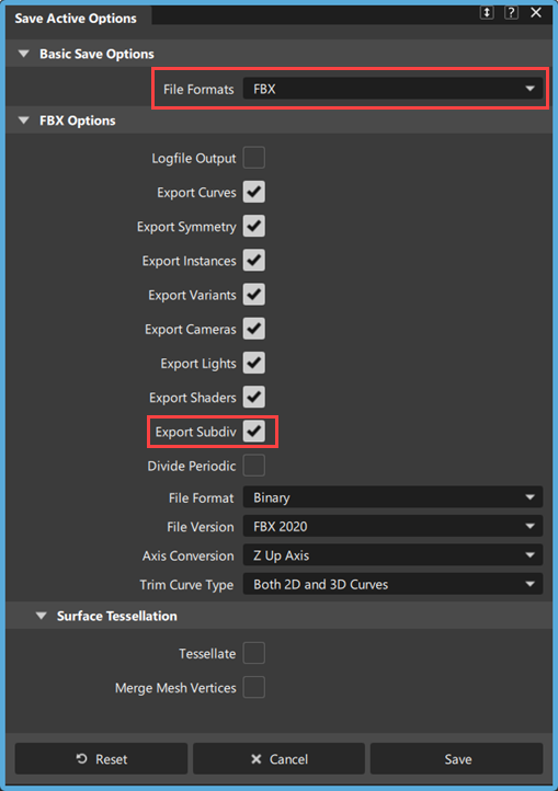
Under the FBX Options, ensure the Export Subdiv is turned on, and then click Save.
Name your FBX file and click Save.
Import the .fbx file into Maya
In Maya, choose File > Import >
.In the Import Options, under General Options, select FBX from the File type list.
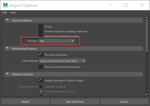
Click Import, browse to your .fbx file, and then cick Import.
You can now edit the Alias subdivision object as a polygon mesh in Maya.
EDF options
Alias saves the following entities to EDF:
- Surfaces
- Curves
- Meshes
- Layer information (layer name and position, according to the selected Order Parts By option)
- Group nodes
- Construction planes
- Materials (wireframe color)
Alias does not save:
- History information
- Image planes
- Symmetry layers
- Layer Set state (Pickable, Reference, Inactive)
- Diagnostic shading
- Lights
- Materials
- Vectors
- Evaluation locators
- Cross sections
- Stitched shells
Options
Export Groups as Molecules
Exports Alias groups as ICEM molecules.
Order Parts by
Sorts Alias layers exported to ICEM parts by Layer Position, Layer Number, or Alphabetically.
Logfile Output
Creates a log file of the results in the same folder as the Alias file. The file has the name [filename].edf.alias2edf.
If Logfile Output is checked on, the following options become available:
Logfile with .txt Extension
Check on this option to create a logfile with a .txt extension, allowing it to be easily opened in any text editor on Windows.
Redirect Logfile Path
Check on this option and specify a folder in the Redirect Path field to write the logfile to that folder. If this option is off, the logfile is saved in the same location as the EDF file.
OBJ options
Object Groups
Default is ON.
Output Units
Specifies the major linear units for exporting the file.
Scale Factor
Specifies the scaling factor for this export. The default is 1.00000.
Surface Tessellation
Tessellate
The default setting is OFF. If set to ON, surfaces are tessellated on export.
Tessellation Tolerance
This option is only visible if Tessellate has been turned on. The value specifies the amount the polygonal surface can deviate from the original NURBS surface.The default value is 0.1.
Normalize UV Coordinates
Turn this on to normalize the surface UV coordinates. This provides better UV coordinates when rendering high-quality images with software renderers such as Arnold.
Related page:
DWG options
Export Invisible
Exports all invisible geometry.
Export Curves
Exports all curve objects.
Export Meshes
Exports all mesh objects.
Want Log
Produces a report containing a list of path names of exported file(s), and a list of warning and/or error messages.
DXF options
Export Invisible
Exports all invisible geometry.
Export Curves
Exports all curve objects.
Export Meshes
Exports all mesh objects.
Want Log
Produces a report containing a list of path names of exported file(s), and a list of warning and/or error messages.
VDAFS options
Include Comments
Determines whether or not comments entered in the Edit File Comments section (found in the VDAFS File Header Information window) are included in the exported file. The default is OFF.
Export Layers
Determines whether or not Alias Layers map to VDAFS groups. The Alias Layer Number is mapped to the group name. The default is OFF.
For example, a layer number of 1 would map to a group name of Layer 001.
Rebuild Geometry
Modifies your models so that all curves and surfaces are compatible with CAD systems or neutral file formats that cannot fully support NURBS geometry by:
- reducing high degree curves and surfaces to degree 3
- making non rational curves and surfaces where rational ones existed before
When Rebuild Surface is set ON, the resulting curve or surface is forced to be at most degree three, with the weight of all CVs equal to a value of 1.
For example, if your model contains curves or surfaces that are rational (with some weights that are not equal to 1.0) or high degree (higher than cubic or bi-cubic), then it is sampled at a number of checkpoints and the data is fit with a cubic or bi-cubic, non-rational curve or surface. Knots are inserted until the fit is within the specified tolerance.
Scale Factor
Lets you save the wire model at a scale other than it was constructed. 1.0 is the default value.
Filename Extension
Some receiving systems require that CAD files have a specific filename extension before they can be recognized. The filename extension specified here is automatically appended to the filename of the exported file.
The default is.vda.
VDAFS File Header Information
Edit File Header
When you click this field, a File Header Information menu is displayed with fields specific to the file format you’ve chosen. Use these fields to communicate information about the model being exported and the sender and receiver of the data. This information is exported in the file header of the file.
These fields are optional.
Edit File Comments
When you click in this field, an editor window is displayed where you can type comments specific to the file you are saving. This editor window can be specified in the General section of Preferences > General Preferences.
Related page:
JAMAIS options
See IGES options and VDAIS options for details on the JAMA-IS options.
File header information
If you choose the JAMA-IS file format, the Save Options window expands to display the following:
Edit File Header
When you click this field, a File Header Information menu is displayed with fields specific to the file format you’ve chosen. Use these fields to communicate information about the model being exported and the sender and receiver of the data. This information is exported in the file header of the file.
These fields are optional.
Edit File Comments
When you click in this field, an editor window is displayed where you can type comments specific to the file you are saving. This editor window can be specified in the General section of Preferences > General Preferences.
VDAIS options
Spline Type, Output Style, Surface Type and Rebuild Geometry are automatically set to the appropriate values when you select a specific vendor from the vendor list.
Spline Type
Lets you choose between B-spline or parametric forms of curves and surfaces to be created in the VDAIS file.
- For B-SPLINE, curves are written as NURBS curves (entity 126) in VDAIS and surfaces as NURBS surfaces (entity 128). This is the default.
- For PARAMETRIC, curves are written as parametric curves (entity 112) and surfaces as parametric surfaces (entity 114).
The PARAMETRIC option does not support high degree or rational geometry. When using this option, any high degree and/or rational geometry is automatically rebuilt to be, at most, cubic and non-rational.
Output Style
Converts surfaces to curves for some drafting packages. If you choose to convert surfaces to curves and have set the patch precision to a number greater than the default, all isoparametric curves are stored in the file.
The default is PRESERVE SURFACES.
Surface Type
Determines whether trimmed surfaces are written as trimmed or bounded. The default is TRIMMED SURFACES.
For TRIMMED SURFACES, trimmed surfaces in the modeler are written as trimmed surface entities (entity 144) and (trim) surface curves are written as curve on surface entities (entity 142) in the VDAIS file.
Level Mapping
Determines the type of Alias information exported as VDAIS Level information.
For LAYER, Alias Layer number information associated to each entity is exported as IGES Level information in the Directory Entry of this VDAIS entity in (field number 5). In this case, Alias SET information is ignored and not exported to VDAIS.
For SET, Alias Set information is exported as IGES Level information. If an Alias Set is given a name of the form LEVEL<n>, where <n> is an IGES level number and greater than 0, then the corresponding VDAIS entity for each member of the Alias Set is assigned to level<n> in the VDAIS file.
For example, the VDAIS entities corresponding to each member of the set LEVEL42 are assigned to level 42 in the VDAIS file. Alias Multi-sets information is exported as VDAIS (type 406, form 1) Property entity definition levels. If an Alias object is a member of several multi-sets that conform to this naming convention, then the VDAIS file contains a Property Entity 406 form 1 (Definition Levels) listing the VDAIS levels to which the corresponding entity belongs. In this case, Alias Layer information is ignored and not exported to VDAIS.
Include Comments
Determines whether or not comments entered in the Edit File Comments section (found in the VDAIS File Header Information window) are included in the exported file. The default is OFF.
Rebuild Geometry
When set OFF (the default), the degree of the resulting surface and the weights on the CVs do not change.
When set ON, models are updated so that all curves and surfaces are compatible with CAD systems or neutral file formats that cannot fully support NURBS geometry by:
- Reducing high degree curves and surfaces to degree 3.
- Making non rational curves and surfaces where rational ones existed before.
The resulting curve or surface is forced to be at most degree 3, with the weight of all CVs equal to a value of 1.0.
For example, if your model contains curves or surfaces that are rational (with some weights that are not equal to 1.0) or high degree (higher than cubic or bi-cubic), then it is sampled at a number of checkpoints and the data is fit with a cubic or bi-cubic, non-rational curve or surface. Knots are inserted until the fit is within the specified tolerance.
Scale Factor
Lets you save the wire model at a scale other than it was constructed. 1.0 is the default value.
Significant Digits
Lets you specify the number of significant digits for coordinate data in the exported file. The minimum number is 1 and the maximum number is 15.
Filename Extension
Some receiving systems require that CAD files have a specific filename extension before they can be recognized. This filename extension specified is automatically appended to the filename of the exported file. The default is.iges.
VDAIS File header information
If you choose the VDAIS file format, the Save Options window expands to display the following:
Edit File Header
When you click this field, a File Header Information menu is displayed with fields specific to the file format you’ve chosen. Use these fields to communicate information about the model being exported and the sender and receiver of the data. This information is exported in the file header of the file.
These fields are optional.
Edit File Comments
When you click in this field, an editor window is displayed where you can type comments specific to the file you are saving. This editor window can be specified in the General section of Preferences > General Preferences.
Common file format descriptions – VDAIS by Vendor
To choose the specific software product to which you are transferring your model, open the VDAIS by Vendor section.
When you choose a specific vendor, your output file is customized to optimize data exchange for the target system. The data exchange parameters (output environment variables) are modified. The active vendor is highlighted.
You can create new vendor files or remove files (except the default) and the By Vendor window is updated accordingly.
IGES options
IGES (Initial Graphics Exchange Specification) is a data exchange format between CAD/CAM systems.
Curves and surfaces are written to IGES as NURBS curves and surfaces. Layer Number information is exported as IGES Level information and can be recognized by each IGES entity. Alias Set information is not exported.
When storing an IGES file, the following options are available:
Shell Type
Lets you preserve surfaces or convert them to curves for some drafting packages.
- The Wireframe option converts surfaces to curves.
- The Solid/Shell option preserves the topology on output. For example, a stitched cube remains a stitched cube, and is not converted to 6 surface faces.
- The Surface option loses the topology on output. For example, a stitched cube is broken into 6 surface faces.
Surface Type
Determines whether trimmed surfaces are written as wireframe, trimmed, or bounded.
- The Wireframe option converts surfaces to curves.
- The Trimmed Surface option writes trimmed surfaces as trimmed surface entities (entity 144) and writes trim curves as curve on surface entities (entity 142) in the IGES file.
- The Bounded Surface option writes trimmed surfaces as bounded surface entities (entity 143) and trim curves as boundary entities (entity 141) in the IGES file.
Output Units
Lets you choose any of the data unit types supported by the IGES standard, including miles, feet, inches, mils, microinches, kilometers, meters, centimeters, millimeters, and microns. The exported coordinate data is converted from the current linear units set in Alias to the units selected here.
An additional choice is available called MODEL, which keeps the output units in the exported file the same as the linear units in Alias (IGES option only).
File Extension
Some receiving systems require that CAD files have a specific filename extension before they can be recognized. The filename extension specified here is automatically appended to the filename of the exported file. The default is sla.igs.
Logfile Output
Creates a logfile containing a list of path names of exported files, and a list of warning and/or error messages.
WARNING
If you create in Alias a surface of revolution with negative angle sweep (the starting angle or/and angle negative) this surface of revolution will be exported to IGES format as a NURBS Surface (IGES entity type 128) and not an IGES Surface of Revolution (IGES entity type 120).
Related pages
STEP options
ISO10303 is a standard for exchange of product information. The standard is organized into a set of Application Protocols (AP). Alias supports three APs:
- ISO10303-203 (Configuration Controlled Design) conformance classes 1-4
- ISO10303-214 (Core Data for Automotive Mechanical Design Process) conformance classes 1-2
- ISO10303-242 (Managed Model Based 3D Engineering), a new single standard that combines all the functionality of the AP203 and AP242 standards
The import and export of this data is supported via ISO10303-21 Physical file exchange.
Application Protocol
Choose AP242, AP214, or AP203 to output the desired STEP file. The default is AP242.
Want Compression
(For AP242 protocol only) Compresses files on export.
Want Grouping
(For AP242 protocol only) Preserves existing groupings.
Want Layers
(For AP242 protocol only) Preserves existing layers.
Want Log
(For AP242 protocol only) Generates a log file containing the time of conversion and the names and types of converted objects.
Model Type
Wireframe models – A collection of curves written out as a Wireframe model.
Surface models – A collection of surfaces written out as a surface model.
Manifold Shells – A collection of stitched surfaces that do not describe a volume is saved out as a G3 Manifold Shell.
Brep Solids – Stitched geometry that describes a closed volume is written out as a G5 Brep Solid.
Hybrid models – A combination of wireframe, surface, manifold shells and BREP solids.
You can save the model and all the geometry in an Alias Stage, into a STEP product. This is performed by choosing the Hybrid Models option (the default).
If, because of contractual or system limitations on the receiving side, a Hybrid model cannot be used, you can select single model representations, as explained in the following table.
| Any Alias Geometry | Hybrid Models |
| Alias Shells (Closed) | G5 BREP Solids |
| Alias Shells (Closed/Open) | G3 Manifold Shells |
| Alias Surface | G2 Surface Models |
| Alias Curves | G2 Wireframe Models |
There is an inherent loss of information outputting an Alias Shell as a wireframe.
When you do not have any shells, you can not get anything from manifold shells option. You can get the unstitched surfaces transferred by using hybrid option.
The other options are selective to shells (only), surfaces (only) or wires (only).
If the Alias model is a set of trimmed surfaces; the model cannot be output as a BREP Solid.
When you choose Model Type option > Manifold Shells or Hybrid Models, two Surface Geometry options are made available.
Surface Geometry
As Is only outputs existing shells.
Add Topology converts all surfaces into shells and outputs the shells.
Trim Curves
Valid when outputting Hybrid Models and G2 Surface Models, this option allows you to output either 2D (parameter space) or 3D (model space) trimming curves.
The default is Parameter Space Trimming.
Keep Multiknots
A multi-knot consists of multiple edit points at the same location in space. Multi-knots are usually the result of curve or surface editing operations that require a sharp turn in a curve.
STEP Header Information
Allows you to attach configuration data to your STEP file.
WIRE options
The default format for the Save command is WIRE, which is the normal Alias binary file format. The Wire Options section displays by default.
Embed Image References
If toggled on, all file texture and environment images used in a scene are embedded into the wire file. This improves your ability to move files around without losing texture and environment images required to render the scene.
Extract embedded images using File > Image References > Extract Image References.
Include Installed Images
Available when Embed Image References is on. If toggled on, texture and environment images from the installed visualization library are embedded into the wire file. Recommended for file sharing with users running older versions of Alias.
Save Information
Lets you add information, such as the name of the individual who generated the .wire file. This text displays in the Information Window.