 Fit Curve
Creates quality curves by fitting to cross-section line data, curves-on-surface, trim edges, isoparms, including surface edges and patch precision lines, and other free curves.
You can fit curves directly to visual cross-sections (without promoting them to geometry first). This helps create geometry from scan data, since cross sections can easily be created on meshes.
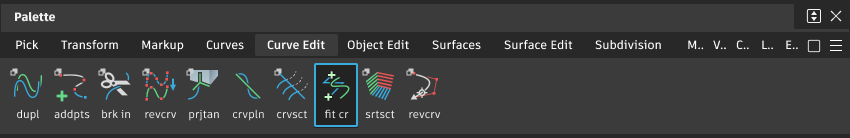
Access this tool from the Curve Edit tool palette:
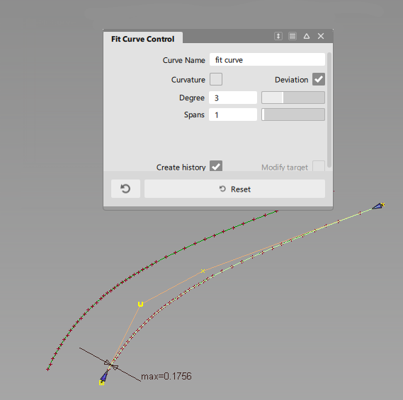
Fit Curve options
Curve Name
Enter a name for the new curve.
Curvature
Turn on this option to show a curvature comb locator on the new curve. This option is off by default.
You can change the comb scale and other settings through the Curvature tool in the Control Panel.
Deviation
Show a maximum deviation locator between the new and original curves. This option is on by default.
Degree
Set the degree of the new curve. Increasing the degree allows a better fit, however not all CAD systems support curve degrees higher than 3 (which is the default).
Spans
Set the number of spans in the new curve. Increasing the number of spans gives a better fit, but also increases the complexity of the model. The default is 1.
Create History
Save the fit curve history for further editing.
When the option is not selected, template curves are not kept when fitting to cross sections, so you do not have to delete them after leaving the tool.
Modify target
This option is only available when fitting a single curve to a curve-on-surface.
If it is checked on, a warning appears, saying that the target curve-on-surface might be modified, and its construction history deleted.
If you choose to proceed, the fitted-curve is projected onto the surface to create a new curve-on-surface. The fitting operation is repeated with the new curve-on-surface as the target. This process continues until a solution (within tolerance - see below) is found.
Max. CoS deviation
This slider controls the maximum lateral distance that the curve-on-surface (the target) is allowed to move when Modify target is turned on.
Buttons
Reset
Clicking this button removes all the fit curve segments on the current target curve. It also restores the original curve-on-surface if it was previously modified by Modify target, but does not restore its construction history.
Fit Curve workflows
Fit a curve to a curve-on-surface, trim edge, etc.
Shift-select the Fit Curve tool.
The control window opens.
Select the curve that you want to fit to (target curve).
The fitted curve is created, using the degree and number of spans in the control window.
The maximum deviation locator appears. (If you do not see it, make sure that the Deviation option is turned on in the control window).
Arrow manipulators appear at both ends of the fitted curve. Single arrowheads mean that the fitted curve extends to the very ends of the target curve.
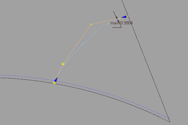
In this example we are fitting a curve to a curve-on-surface.
If the deviation is too large, open the control window and do one of the following:
- Increase the Degree
- Increase the number of Spans
- Turn on Modify target and adjust the Max. CoS deviation to the maximum lateral distance that the curve-on-surface (the target) is allowed to move.
Note: Modify target is only available when fitting a single curve to a curve-on-surface.If Modify target is on, a warning appears, saying that the target curve-on-surface might be modified, and its construction history deleted. If you choose to proceed, the fitted-curve is projected onto the surface to create a new curve-on-surface. The fitting operation is repeated with the new curve-on-surface as the target. This process continues until a solution (within tolerance) is found.
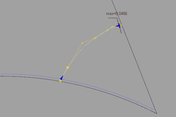
Changing the degree to 5. Max deviation is reduced to 0.0456.
Whenever an option changes in the control window, the fitted-curve is re-calculated and updated.
To fit the curve to only a portion of the curve-on-surface, drag the arrow manipulators.
When dragging the arrow manipulators on a fitted curve, snappable points appear automatically (without having to hold any control keys).
Light blue segments indicate snap divisions (equally spaced along the fitted curve).
Pink crosses indicate locations where the fitted curve intersects other curves or surfaces in the current view.
The fitted curve and maximum deviation measurement update.

Click on the remaining part of the curve-on-surface to fit a curve to that portion only.
A second fitted curve appears, with its own maximum deviation locator and arrow manipulators.
 Note: You can also select additional curves to fit.
Each fitted curve can be selected independently and edited using the options in the control window and the arrow manipulators.
Using Ctrl + X or the Delete key deletes the currently selected fit curve segment.
Using Ctrl + Z or Edit > Undo sequentially undoes changes to the arrow manipulators of the currently selected fit curve segment. It does not apply to the deletion of a fit curve.
Fit a curve to a visual cross section
The workflow to fit a curve to a visual cross-section is the same as above. Here is what happens differently:
- The visual section is automatically promoted to section data, using tolerance settings from the Promote tool in Windows > Cross Section Editor.
- A NURBS curve is fitted to the section data, and its construction history is connected to the section data (and not to the surface, mesh, or visual section).
- The fitted curve and the promoted section data are grouped.
- The section data is templated.
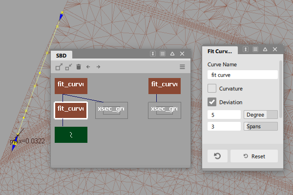
Degree 3 curves fitted to a visual Z cross-section on a mesh.
You can modify the inputs (degree, spans, and so on), just as with any other fitted curve.
If you click Reset after fitting a curve, the curve and the templated section data are both deleted.
If you exit the tool, the fitted curve has construction history linked to the section data. You can choose Object Edit > Query Edit, then select the curve to re-enter the Fit Curve tool as usual.
If the construction history is removed, the templated section data stays behind.
Create a high-quality NURBS curve from scan data.
Section data in reference layers can be selected from within this tool.
Shift-select the Fit Curve tool
.The control window opens automatically.
Click the scan line (section data).
A NURBS curve is fit to the section data.
Do any of the following:
Drag the start and end point manipulator arrows to control which part of the scan line the curve is fit to. Usually you will want to fit curves to sections with little curvature.
When dragging the arrow manipulators on a fitted curve, snappable points appear automatically (without having to hold any control keys).
Light blue segments indicate snap divisions (equally spaced along the fitted curve).
Pink crosses indicate locations where the fitted curve intersects other curves or surfaces in the current view.
Turn on the Curvature option to show a curvature comb plot on the new curve.
Turn on the Deviation option to show the maximum deviation between the new curve and the scan line.
Adjust the Degree and Spans settings in the Fit Curve control window to try to achieve a better fit. Increasing these values will make the curve fit the scan line better, but will also give you a more complex curve.

The new NURBS curve has construction history.