 Curve & COS Offset
Creates an offset curve with the specified distance from the original curve. The distance of a Curve-on-Surface offset is measured on the surface.
For each selected curve chain, a vector handle is displayed in the graphics area to control the offset distance and direction.
Access this tool from the Curves tool palette:

Curve & COS Offset Control
Offset Mode & Distance
Automatic
Creates a quick offset that allows you to specify the Deviation Tolerance. Spans are edited (added or removed) until the specific deviation tolerance is reached, or the maximum number of spans are reached.
CV Offset
The structure and parameterization of the original curve is used as input. Each CV is moved in a certain local offset direction as far as required to get the most accurate result.
Explicit
Allows you to control the degree and the number of spans for the curve offset.
Original
The curve offset is created based on the original degree and the original number of spans, but the parameterization is adapted to the new shape.
Offset Distance
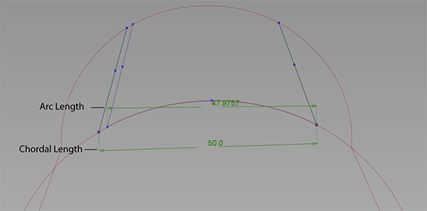
Specifies the distance between the original curve and where the curve offset is created. You can specify whether you want this distance to be measured according to chordal length or arc length. You can specify a positive or negative Offset Distance value to create a curve offset on either side of the original curve. You can also drag the arrow head in either direction to change the Offset Distance value positively or negatively.
Offset Measure
Specifies the method used to measure the Offset Distance. These options are only available when the input is a surface edge, curve on surface, surface span, or isoparm. It is not available when offsetting a Curve.
Chordal Length – Offset distance is based on the shortest linear distance between input and offset output. Use this option when you want a linear offset distance. Chordal Length is the default method.
Arc Length - Offset distance is based on the arc length of the input surface. Use Arc Length when you want the offset length measured on the surface length.

Explicit Control Options
Explicit Degree
Allows you to specify an explicit degree for the curve offset. This option only appears if the Explicit offset mode is selected.
Min Degree
Allows you to specify a minimum degree value for the curve offset. This option only appears if the Explicit offset mode is selected.
Degree
Specifies the explicit degree value if Explicit is selected or the minimum degree value if Min is selected for the curve offset.
Explicit Spans
Allows you to specify explicit U and V spans for the curve offset. This option only appears if the Explicit offset mode is selected.
Max Spans
Allows you to specify a maximum number of spans for the curve offset. This option only appears if the Explicit offset mode is selected.
Spans
Specifies the explicit number of spans if Explicit is selected or the maximum number of spans if Max is selected for the curve offset.
More Options
Deviation Tolerance
Controls the accuracy of the offset result. The Deviation Tolerance option is only available if the Automatic offset mode is selected, or if Max Spans is selected under Explicit Control Options.
Min. Spans Length
Specifies the minimum length of spans in the curve offset. The Min. Spans Length option is only available if the Automatic offset mode is selected, or if Max Spans is selected under Explicit Control Options.
Extend
When offsetting two or more curves, enabling the extend option extends the curves until they intersect.
Attach
Offset curves are attached together as one curve, and redundant CVs are removed. If this option is disabled, each curve is offset separately.
Both Sides
Creates an offset curve on both sides of the original surface. The Offset values apply to both offset curves. The offsets of the curves cannot be controlled independently.
Cut Curve Loops
If this option is enabled, all loops inside the curve offset result are eliminated.
Blend
Closes gaps in the offset result by extrapolating the curve ends until they meet or creating a blend curve with transition continuity of G1 or G2.
G1/G2
Specifies the transition continuity of the curve offset.
Offset Plane
X, Y, Z
Applies an offset that is perpendicular to the direction of the specified plane's normal direction. For example, selecting X generates an offset that is parallel to the X plane.

View
The offset is created according to the plane that is parallel to the camera view.
Picked
The offset is created according to the vector that you pick in the viewport.
Auto
The offset plane is automatically calculated.
Control Options
Auto update
If selected, any changes in any field of the control box lead to an automatic update of the model display. Auto Update is enabled by default.
Show Curvature
Shows the curvature of the curve offset. Show Curvature is disabled by default.
Show Deviation
Shows the deviation of the curve offset. Show Deviation is disabled by default.
Create History
Saves the history of the curve offset so you can modify the offset later. Create History is enabled by default.
Create Metadata
Specifies whether the Curve & COS Offset tool creates history metadata. Create Metadata is enabled by default.
Chain Select
If this option is selected when you select a curve, all curves that are tangent continuous are selected. Box select curves with Selection Options enabled to add or remove individual curves.
Curve and COS offset workflow
Offset a curve using the Curve & COS Offset tool
Select the tool.
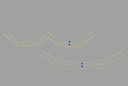
Pick the curve you want to offset. The offset appears in a different color than the picked curve with an arrow indicating the direction of the offset. The image below displays offsets of multiple curve and an offset of single curve.

Do any of the following:
Drag the arrow left and right using the
 to change the offset distance. You can also change the offset direction by dragging the arrow head or clicking the base of the arrow.
In the Curve & COS Offset Control window, type a number or use the slider to set the Offset Distance exactly and specify other options for the offset.
Note: You can specify a positive or negative Offset Distance value to create a curve offset on either side of the original curve.Specify whether you want the Offset Distance to be measured by chordal length or arc length by setting the Offset Measure option. For more information, see Offset Measure.
Select additional curves (or de-select them) by holding the
 key while clicking them or using a pick box.