New CV Curve
Creates new NURBS curves in the scene by placing CVs.
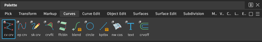
Access this tool from the Curves tool palette:
Related video
New CV Curve Options
Knot Spacing
A “knot” is the parameter value at an edit point.
Chord – The chord length parameterizes the new curve edit points in current units. The chord length is the cumulative straight line distance between consecutive edit points. The starting point of the curve has the parameter 0.0, and the ending point has the parameter equal to the total chord length of the curve.
Uniform – The new curve edit points have integral parameters: the first edit point is parameter 0.0, the second is 1.0, and so on.
Curve Degree
The mathematical degree of the curve created, which control the number of CVs per span: 1 (linear), 2 (quadratic), 3 (cubic), 5 or 7. The default is 3.
Progressive Degree
Turn on this option to see the curve immediately after two CVs have been placed, regardless of the value of Curve Degree.
The degree of the curve is gradually increased as CVs are placed down, up to the final degree of the curve. After two CVs, the curve will have degree 1, after three CVs, the curve will have degree 2, and so on.
Pivot Position
Specifies the initial position of the curve's pivot points (both rotation and scaling).
Origin – The pivot points are located at (0, 0, 0).
First CV – The pivot points are located at the position of the first CV, that is, the start of the curve. This is the default.
Last CV – The pivot points are located at the position of the last CV, that is, the end of the curve. The pivots position is re-calculated and displayed every time a new control point is placed.
Curve center – The pivot points are located in the middle of the curve, based on arc length. (This is the same position as Snap to Center in the Curve Snap Options box.) The pivots are placed at the first CV until there are enough CVs to form a span, and then are re-calculated and displayed every time a new span is created.
Bounding box center – The pivot points are located at the center of the curve's bounding box. The pivots position is re-calculated and displayed every time a new control point is placed.
Create Guidelines
Create vertical and horizontal guidelines at each point you create.
Show Pick Chooser
The pick chooser appears when CVs are snapped to coincident curves.
New CV curve workflow
To set what parameterization and degree the curves you draw will have, open the tool’s option box and set the Knot Spacing and Curve Degree options.
Draw curves by placing CVs
Shift-select the tool
.Click in view windows to place the CVs of the new curve, or type coordinates for the CV locations.
For a degree 3 curve (default), the curve will only appear after 4 CVs have been placed.
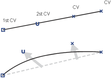
Note: The general rule is that a curve of degree m requires m+1 CVs before becoming visible. To see the curve sooner, turn on Progressive Degree in the option box.Tip: The first CV in the curve is shown as a square and the second as a “U” instead of a cross. This helps show the direction of the curve.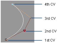
Choose the tool again to start another curve.
Edit curve workflow
Move a point on a curve to touch another curve
- In the Pick tool palette, click the Edit Point tool
 to select the edit point you want to move.
 - In the Transform tool palette, select the Move tool
 .
. - Hold
CtrlandAltto turn on curve snapping. - Click the curve you want to move the point onto. You can drag the point along the curve.
About CVs, hulls, and edit points
About CVs
CVs (control vertices) control how the curve is “pulled” from a straight line between edit points. They are the most basic and important means for controlling the shape of a curve. Lines between consecutive CVs form the control hull.
You cannot add CVs to the interior of a curve: there is always a set number of CVs for each span. The number of CVs is equal to the degree of the curve plus one. So, for example, a degree 3 curve has four CVs per span.
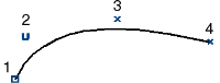
Alias draws CVs differently to let you tell the difference between the start and the end of a curve. The first CV (at the start point of the curve) is drawn as a box. The second CV is drawn as a small “U”, to show the increasing U dimension from the start point. All other CVs are drawn as small Xs.
About multiple spans
Longer and more complex curves require more than a single span curve. As you draw what appears to be a single long curve, Alias is actually adding several curve spans together. The last CV of the previous curve span become the first CV of the next curve span, creating very smooth transitions between the curve segments.
About edit points
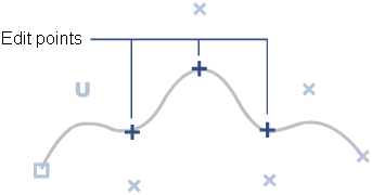
You can tell when a curve is made from multiple spans in several ways. One is to look for edit points on the curve. Edit points mark the connection point between two spans. Alias draws edit points as small crosses.
Unlike the on-curve control points of Bezier curves (used in many 2D illustration programs), NURBS edit points are not usually used for editing curves. CVs control the shape of a NURBS curve, and edit points are just indicators of how many spans a curve has.
About hulls
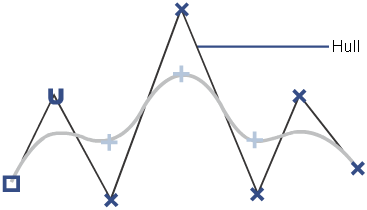
As a curve gets more spans/edit points, you might lose track of the order of the CVs. To show the relationship between CVs, Alias can draw lines between them. These lines are called hulls.
About curve or surface degree
bout curve or surface degree
Degree is a mathematical property of a curve or of a surface dimension that controls how many CVs are available for modeling.
The number of CVs for each curve span is controlled by the degree of the curve. The default curve type in Alias is degree 3, which has four CVs for the first curve span.
You can choose to have fewer CVs per span or create curves with more than four CVs per span.
- Degree 1 creates curves or surfaces with straight lines.
- Degree 2 curves or surfaces do not automatically have smooth transitions between spans or patches.
- Degree 3 is the default degree for new curves and surfaces.
- Degree 5 and degree 7 curves are generally used in automotive design. They are slower, but give you smoother curves, better internal continuity, and more control.
The degree of your curves can affect data transfer to CAD packages. Some other packages cannot accept curves with degree higher than 3.
Surfaces can have different degrees across their width and length. So, for example, a surface could be degree 3 along its width, and degree 5 along its length.
About parameters and parameterization
Parameters are the unique numeric values (like a coordinate) of points on a curve or surface. You can think of a curve as made up of an infinite number of points. Each of these that make up a curve has a number, called its parameter. The higher the parameter, the further is the point along the curve.
Just as points in space have three dimensions, called X, Y, and Z, the parameters of a point are measured along the one internal dimension (length) of the curve. We call this dimension U.
Since surfaces have two internal dimensions (length and width), we need another parameter (in addition to U) to specify a point on a surface. We call this parameter V.
Just as every point along the length of a curve has a U parameter, every point across a surface has a pair of U and V parameters.
What is parameterization?
The method Alias uses to number the points along a curve is called the parameterization of the curve. Alias has two parameterization methods: uniform and chord-length.
Each method has advantages and disadvantages depending on how the curve is used. You can choose which parameterization method to use when you create a curve, and you can rebuild existing curves to use a specific parameterization.
Uniform Parameterization
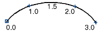
Uniform parameterization assigns integral parameter values to the edit points, and evenly distributes parameters along the spans between edit points. So the first edit point is always parameter 0.0, the second edit point is always 1.0, the third is always 2.0, and so on.
A bonus feature of uniform parameterization is that the parameter value of the last edit point is the also the number of spans in the curve. However, unlike chord-length parameterization, the parameters of a uniform curve have nothing to do with the actual length of the curve.
Chord-length Parameterization
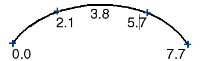
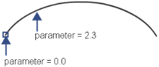
Chord-length parameterization assigns parameter 0.0 to the start of the curve, then increases the parameter value proportionally to the chord length, or the shortest linear distance, between the surrounding edit points.
Unlike uniform parameterization, the parameters of a chord-length curve are irregularly spaced between the edit points, and the edit points do not have integral parameters.
Comparison
Each parameterization method has advantages and disadvantages, depending on how you use the curve or surface.
| Type | Pros | Cons |
|---|---|---|
| Chord-length | Parameter value gives some indication of the relative position of the point along the curve. Minimizes stretching and squeezing of textures. | Parameters are not obvious. Surfaces built from chord-length curves can be more complex because of cross-knot insertion. |
| Uniform | Easy to reckon parameters (for example, 1.5 is about half-way between edit points at 1.0 and 2.0). | In many cases, interpolation between edit points is not as good. Can lead to unpredictable stretching of textures during rendering. |
Just as with degree, surfaces can have different parameterization methods for their U and V dimensions. For example, the U isoparms of a surface can be degree 3 with uniform parameterization, while the V isoparms are degree 1 with chord-length parameterization.
About constructing quality curves
Use the simplest curves that can describe the shape you want. Simpler curves mean simple, faster rendering surfaces.
One effective method for achieving simple curves is:
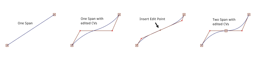
- Begin a curve by drawing a single span.
- Move the CVs to achieve the shape you want.
- If you can’t achieve the shape, add an edit point to create more CVs.
- Continue until you have the shape you need.
This iterative process ensures that your curve only has as many spans as are absolutely necessary.
You can also use the Rebuild curve tool to simplify existing curves. The tool can simplify a curve while maintaining its shape within a tolerance you set.
Parameterization
It is often best to build curves with uniform parameterization, because it makes inserting edit points and detaching curves at exact locations easier.
- When drawing Edit point curves with Uniform parameterization, the resulting CVs may be placed awkwardly. To fix this, move the CVs to prevent crossing hull lines.
- Try to use either Uniform or Chord length parameterization consistently when drawing curves. If you mix and match curve styles, it could result in cross knot insertion when the curves are used to build a surface.
Intersections
Some surfacing tools require curves to intersect:
To draw intersecting curves, use curve snapping (hold down
Ctrl+Alt, or click the curve snapping button to the right of the prompt line).
To make existing curves intersect:
- Pick an edit point and use the Move tool with curve snapping.
- Use the Object editor with curve snapping.
Planning for surfaces
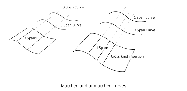
When creating curve, plan ahead to the surfaces that you want. Try to have the same number of spans in all the construction curves for building a surface. A simple way to achieve this is to start with one curve, then duplicate it to create more construction curves.
When you create a surface from curves with different numbers of spans, the new surface has an extra isoparametric curve corresponding to every extra edit point. This is known as cross knot insertion. It makes the new surface more difficult to edit and more complex.
About laying out curves and surfaces
As you create curves and surfaces, or fit curves and surfaces to scan data, you have to decide how to use separate surfaces to create the overall model.
For all but the very simplest models, you do not want to create the entire model using a single surface. Sometimes the choice of boundaries between separate surfaces is obvious. But in cases where there is no clear natural boundary, you have to decide how to break up large-scale areas into individual surfaces.
This is decision is a bit of an art, with different modelers making different decisions to emphasize different priorities.
Deciding where to separate surfaces
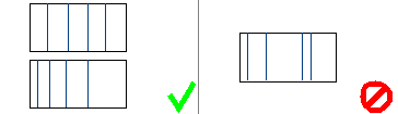
Consider the following cross sections:
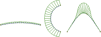
The shape on the left has low curvature. The shape in the middle has high curvature. The shape on the right has two changes in curvature.
You want to break up large-scale areas into areas of low curvature and high curvature at the points where the curvature begins to increase.
In areas of low curvature, you don’t need as many CVs to describe the shape, so you can use a single span and a lower degree curve. Using separate surfaces for these areas lets you use simpler geometry.
In areas of high curvature, you need more CVs to describe the shape more accurately. Using separate surfaces in these areas lets you use high degree surfaces or multiple spans to get more CVs. Note that even if you can “get away with” describing the shape with a small number of CVs, the CVs may be doing too much work. That is, each CV is responsible for controlling such a large area of the curve or surface that making small changes to the curve or surface later will be very difficult.
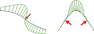
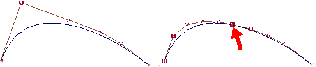
You want to break up shapes where the curvature changes direction (called inflections, shown in the following image on the left), and where curvature begins to change (shown in the following image on the right).
CV distribution
In each case, breaking the model up involves maximizing the use of CVs. That means creating conditions where no CVs are “overworked” (having too much influence on the shape of the curve or surface), and the CVs have a smooth distribution, both of which make maintaining shape and continuity easier.
Overworked (or high tension) CVs are CVs that are distant from the curve they control, or have a significant influence on the shape of their curve or surface.
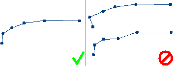
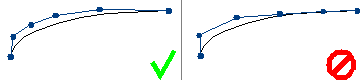
In the following simplified example, the second CV in the curve on the left is clearly doing a lot of work: it’s almost solely responsible for pulling the shape of the curve to the left.
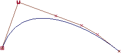
This makes editing the shape of the curve difficult. Because a single CV is largely responsible for the shape of a section of the curve (marked in the following image), and any reshaping you want to do anywhere within section must be accomplished by moving that one CV.
This leads to extremely minute and frustrating adjustments of the CV, as you find each movement affects a larger area than just the small part of the curve you wanted to improve.
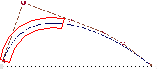
Using separate curves (as shown in the following image on the right) immediately improves the situation. Now each CV in both curves is exerting roughly the same amount of influence.
A good distribution:
Puts more CVs in areas of high curvature.
Has even or smoothly changing spacing between hulls.
Has consistent direction change along hulls, with no zigzags, W shapes, or pronounced peaks.