 Deviation Map
Shows the deviation (distance) between a set of meshes and a set of NURBS surfaces as a colored error map on the surfaces. You can also show the deviation between two sets of surfaces, or two sets of meshes.
Access this tool from the Evaluate palette:

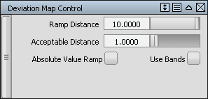
Deviation Map Control
Ramp Distance
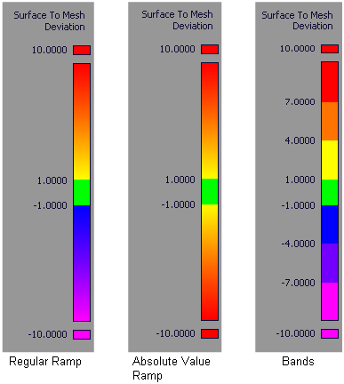
Maximum distance between surfaces and meshes shown on the color ramp. Areas on surfaces where the deviation is larger than this value are displayed in a solid color (red or purple). The default is 10.0.
Acceptable Distance
Upper limit for the acceptable deviation between meshes and surfaces. Regions of the surfaces where the deviation is smaller than this value are colored in green. The default is 1.0.
Where the value of the deviation is between the Acceptable Distance and the Ramp Distance, the surfaces display intermediate colors as shown on the ramp.
Absolute Value Ramp
Turn on this option if you are not concerned with the direction of the deviation and simply want to view absolute deviation values.
Use Bands
Turn on this option if you want the ramp to display solid bands of color instead of slowly varying colors.

Deviation Map workflows
You can show a colored error map of the deviation (distance) between a set of meshes and a set of NURBS surfaces, or between two sets of meshes, or between two sets of NURBS surfaces.
Display a Mesh-to-Surface deviation error map
Select one or more surfaces, then click the Accept button.
Select one or more meshes, then click the Go button.
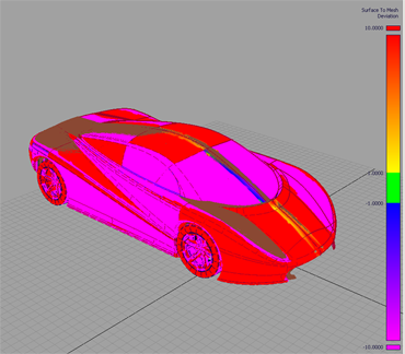
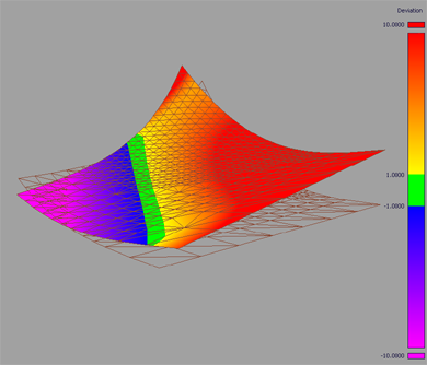
The deviation error map appears on the surfaces and a color ramp (deviation ramp) is displayed.

Display a Surface-to-Surface deviation error map:
Select one or more surfaces.
Press the Accept button.
Press the Surfaces button.
Select the second set of surfaces.
Press the Go button.
The deviation error map appears on the first set of surfaces and a color ramp (deviation ramp) is displayed.
Display a Mesh-to-Mesh deviation error map:
Press the Mesh button
Select one or more meshes.
Press the Accept button.
Select the second set of meshes.
Press the Go button.
The deviation error map appears on the first set of meshes and a color ramp (deviation ramp) is displayed.
 Note: The first set of meshes or surfaces can also be selected before entering the tool.
Adjust the display of the color ramp
The color in the center of the ramp (green) identifies regions where the deviation is within an Acceptable Distance value. The colors at both ends of the ramp identify regions where the deviation is above a certain maximum value (Ramp Distance) in either direction. Between these two values, the surface displays intermediate colors as shown on the ramp. The color distribution on the ramp can be adjusted as follows:
Double-click the tool to open the option box.

Use the Acceptable Distance and Ramp Distance sliders to modify the tolerance bands in the color scale.
The deviation error map on the surface(s) updates.
Note: The Ramp Distance is the maximum distance between surface and mesh shown on the color ramp. It should be kept larger than the Acceptable Distance.Turn on the Absolute Value Ramp option if you are not concerned about the direction of the deviation and only want to see absolute deviation values.
Turn on the Use Bands option if you want the ramp to display solid bands of color instead of slowly varying colors.
Remove the deviation map
The deviation error map is persistent during tumbling or other view manipulation. Modifications to the geometry cause the error map to update.
- To remove the map, select the Shading Off button in the Diagnostic Shading