 Symmetric Modeling
Makes the selected geometry symmetric. This lets you modify the controls (CVs, edit points, blend points) on one side, while the corresponding controls on the symmetric half update automatically to maintain the symmetry.
Access this tool from the Object Edit tool palette:
About Symmetric Modeling
The symmetry plane is defined by the default symmetry plane for the layer the curve or surface belongs to (Y=0 by default). This plane can be modified by using Layers > Symmetry > Set Plane.
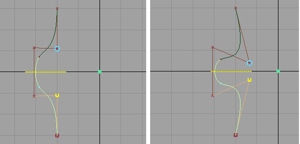
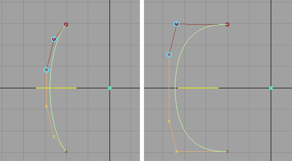
Moving the bottom CV automatically moves its symmetric twin (blue circle) in the opposite direction to maintain the symmetry.
After the curve or surface has been made symmetric, any transformation tool can be applied to the controls.
Inputs and selection
- Any type of curve or surface can be selected. The modified controls can be CVs, edit points, and blend points. If moving keypoints, the curve loses its keypoint attributes.
- For blend curves, only the position of the blend points is supported by symmetric modeling (and not other constraints such as tangent scaling). Blend curves where any blend point is connected to geometry are not supported.
- Several curves and surfaces can be selected at once, either before or after entering the tool.
- Symmetry constraints are applied to each curve or surface individually.
Modification
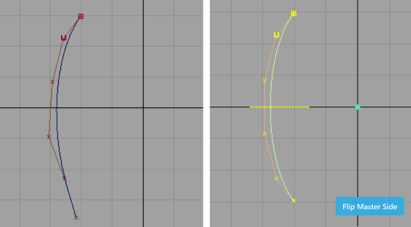
If the input curve or surface is not symmetric, the tool modifies the controls of the model to ensure that it is symmetric. It applies the position of the controls from the beginning of the curve or surface to the symmetric partners at the end of the curve or surface. Click the Flip Master Side button to have it work the other way around.
Note: If the curve or surface was already symmetric, the Flip Master Side button does not appear.If a control (CV, edit point, or blend point) is selected prior to entering the Symmetric Modeling tool, the side of the object containing the picked control becomes the master side and is not modified when the object is made symmetric.
Any transformation tool can be applied to the controls including Move, Rotate, Scale, Non Proportional Scale, Move CV (XYZ, Slide, NUV, Project) or Proportional Modification.
Once the Symmetric Modeling tool has been applied to a curve or surface, the controls respond to any transformation by also modifying their symmetric partner across the plane of symmetry.
Symmetry plane
The initial symmetry plane location and axis direction is defined by the layer symmetry plane. By default this plane is defined as Y=0 (XZ plane).
A symmetry plane is assigned and displayed for each object selected.
The symmetry plane for a layer can be modified through Layers > Symmetry Plane > Set Plane. This does not affect the symmetry plane assigned to any curve or surface through the Symmetric Modeling tool.
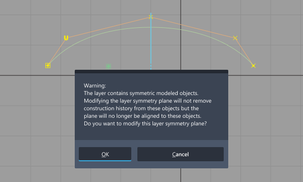
Once defined, the symmetry plane is unique to each curve or surface. When a curve or surface is transformed, its symmetry plane becomes decoupled from the layer symmetry plane, and follows the object. If the plane doesn’t match the layer symmetry plane anymore, it is drawn in a different color. A confirm box also appears in this case.
Undo
- If a curve or surface is modified while establishing symmetric constraint, you can use Edit > Undo
Ctrl+ Z to return it to its original state. Similarly, Undo works with any symmetric modification to the controls, up to the limit specified in Preferences > General Preferences. - You can return a curve or surface to its normal state (without symmetric constraint), while maintaining the modifications to the controls, by removing the construction history with Delete > Delete Construction History, or by using the History View window.
Symmetric Modeling workflow
In this example, we'll assume a curve has been created across the Y axis and modify it across the centerline.
Select the Symmetric Modeling tool.
Select the curve.
If the curve is not already symmetric, the tool modifies the controls to make it symmetric. The position of the controls from the beginning of the curve are applied to the symmetric partners at the end of the curve. Click the Flip Master Side button to have it work the other way around.
Note: Several curves (and surfaces) can be selected at once. Symmetry constraints are applied to each curve (or surface) individually.A yellow symmetry plane is displayed. This plane corresponds to the default symmetry plane for the layer the object belongs to (XZ plane by default). You can modify it by using Layers > Symmetry > Set Plane.
Pick one or more CVs on one side of the curve.
Blue circles appear around the corresponding CVs on the symmetric half.
Move the CVs. You can use any transformation tool, such as Transform > Move or Control Panel > Transform CV.
The selected CVs follow the mouse. The symmetric CVs move in the opposite direction on the symmetric side of the plane.
Note: To have the symmetric CVs update as you drag the mouse, turn on During Transform in the Construction History Updates section of Preferences > Performance Options.The curve has construction history so that any subsequent operation on the CVs will continue to maintain symmetry across the plane. If you want to remove the symmetry constraint from the geometry, delete the construction history (Delete > Delete Construction History).
If you move the curve, the symmetry plane moves with it but is drawn in a different color to differentiate the curve from symmetric objects still aligned to the layer symmetry plane. A confirm box warns you. Clicking Cancel undoes the transformation.