 Transformer Rig
The Transformer Rig sets up construction history; the actual modification of the model happens “outside” of the shape modeling tool, and is performed by moving and modifying CVs of the modifiers.
The modifiers are specific to each model, and must be created specifically for the model. You are free to do anything you want to the modifier to express the shape change you want. Slide CV, scale, add spans, or change degree of the geometry. The only limitation is that you must not detach or merge geometries.
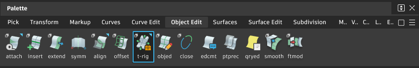
Access the Transform Rig from the Object Edit tool palette:
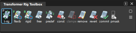
Transformer Rig toolbox
Selecting the Transformer Rig icon ![]() Transformer Rig opens the toolbox:
Transformer Rig opens the toolbox:
![]()
Transformer Rig
![]()
This tool is the first tool to choose when adding a rig to a model. It enables you to choose what to modify. See Transformer Rig general workflow for information about how to create a rig.
Double-click or ! Shift-click this icon to open the option window. You can only open the window after a target has been chosen. Use the settings in the window to:
- Change the visibility of the original and target geometry
- Choose the fitting method for global NURBS shaping
For more information, see Transformer Rig Options.
Add Flexible Targets
![]()
Flexible targets are surfaces, curves, or meshes that can have their shapes changed by applying transformations to the rig.
To add flexible targets, click this icon and select the geometry to assign as targets, then click Accept Targets. To remove targets, choose the Remove from Rig tool in the toolbox.
Add Rigid Targets
![]()
Rigid targets are surfaces, meshes, or curves. They transform (translate and/or rotate) along with the modification, but keep their shape; that is, the targets do not scale or shear.
To add rigid targets, click the icon and select the geometry, then click Accept Targets. To remove targets, choose the Remove from Rig tool in the toolbox.
Use the  on a target to open a pop-up menu that enables you to lock the movement direction for the rigid targets.
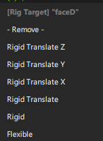
If Rigid is selected, the target is free to rotate and translate in all directions. Rigid Translate only allows translation to occur: the target is not rotated. Further restrictions can be used with the X, Y, and Z constraints, which allow translation to occur in only one specific world-space axis direction (note: this does not respect construction planes). You can also change the type of target from Rigid to Flexible, or vice-versa.
Add Free Modifiers
![]()
A free modifier is a surface or curve used for shaping all the selected targets at one time. Use this tool to designate geometry as free modifiers, and then manipulate this geometry using regular Alias functionality to effect changes to the target geometry.
Add Predefined Modifiers
![]()
A predefined modifier is a pair of similarly parameterized geometries.
- The modifier selected first is the current status of the targets;
- The modifier selected second indicates the shape the targets should have after the modification.
- To use predefined modifiers,
- First select the geometry that is the origin, and click Accept Origin.
- Then click the geometry that represents the final shape, and click Accept Destination.
- If there are several pairs of predefined modifiers, perform the sequence of defining the original geometry and the destination geometry for a pair, and choose the Add Predefined Modifiers tool again to add a subsequent predefined modifier. You cannot select several different origin curves (or several chains of curves) followed by several destination curves (or chains of curves).
Add Constraints
![]()
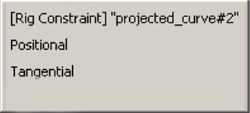
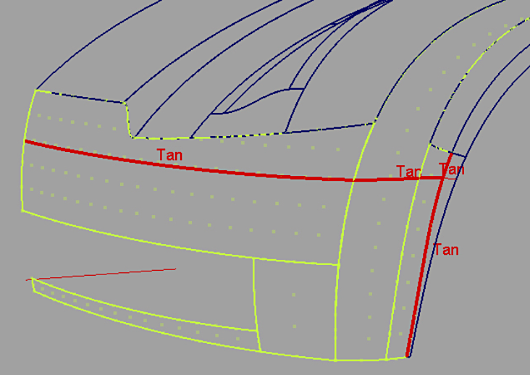
Constraints define a region of the model that should not be modified, and also delimit the range of modification. The continuity along the constraint can be fixed as positional or tangential. Using the to click a constraint opens a pop-up menu to change the continuity quality of the constraints. The default is for the constraints to be tangentially continuous.
Add Clampers
![]()
Clampers can help the software recognize regions of the model that should not be modified. These regions are usually defined by the constraints, but in some cases, the help of a clamper or clampers is needed. These regions can be identified with the help of the green and red dots that appear when setting constraints. These dots appear when Clamp Visualization is checked in the option box.
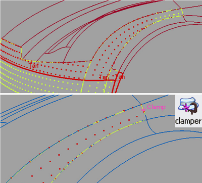
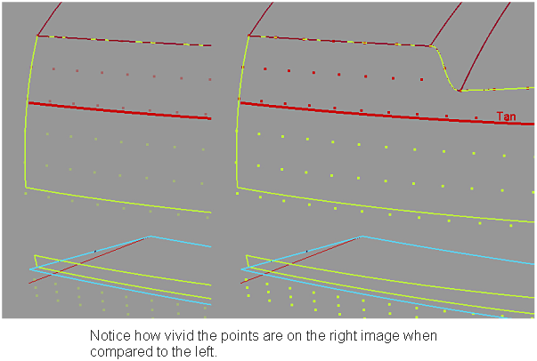
The region with green points is the region that is free to be modified. The region with red points is fixed, and will not change. To improve the visualization temporarily, pick a dot with the middle mouse button to make the colors more vivid.
Remove from Rig
![]()
Choose this tool to remove targets, modifiers, constraints, or clampers from the rig. You can pick constraints, modifiers, or targets, and clampers. The geometry picked for removal is highlighted in yellow. To confirm the removal, click the Remove Selected button in the lower right corner of the view. To cancel the operation, click Cancel.
Revert
![]()
When targets are added to the rig, they are duplicated. The shape modifications are performed with this duplicated geometry. To restore the original geometry and to delete the modified geometry and history, click Revert. Notice that the manipulated modifiers do not return to their status before the dynamic modeling.
Commit
![]()
Click Commit to confirm the dynamic shape modification and delete the original geometry and the history.
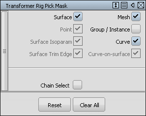
Show Pick Mask
![]()
This tool helps when selecting items for use in the rig, because you cannot use the Pick Components tool inside the Transformer Rig. Notice that the edge of a trimmed surface is not a surface isoparm, it is a surface trim edge.
![]()
Click the check boxes to set an entity type.
Transformer Rig Options
To see the Options window while in the tool (you must have some geometry already accepted as a target), hold the Shift key and click the Transformer Rig tool icon in the toolbox, or double-click the tool icon.
To see the Options window while outside the tool, first re-enter the tool by selecting Query Edit![]() then select an object that has dynamic shape modeling history. Hold the
then select an object that has dynamic shape modeling history. Hold the Shift key and click the Transformer Rig tool icon in the toolbox.
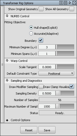
Show Original Geometry
If checked, this box enables the display of geometry as it was before the Transformer Rig tool was applied. If unchecked, the current version of modified geometry is displayed. Use this feature to flip and compare “before” and “after” geometry.
Show All Geometry
If checked, this box enables the display of both the original and deformed geometry.
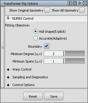
NURBS Control
The fields in this section control the way the Transformer Rig tool modifies NURBS target surfaces. Settings in this window have no effect on meshes that were selected as targets. If all targets are meshes, or if Mesh Output is set, this section of the control window is hidden.
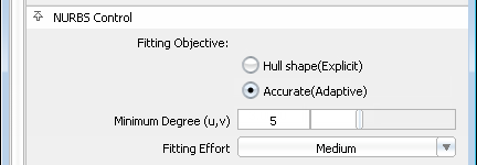
Fitting Objective
The available methods are:
Hull Shape (Explicit) – Optimizes fitting for hull shape. This option allows for explicit control of minimum degree and spans. If the boundary field is checked, the fitting is optimized for patch boundaries.
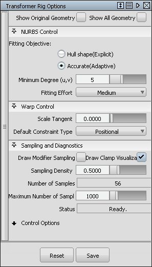
Accurate (Adaptive) – Optimizes fitting for accuracy. This determines the minimum number of spans necessary for an accurate representation of the modified shape.
The Fitting Effort option has been reorganized to a pull-down menu with Low, Medium, High, and Custom values. If Custom is selected, a slider can be used to set the value precisely.
Minimum Degree (u,v)
Specifies the minimum degree of resulting patches. If a patch target has degree less than the specified degree, its degree is raised to the specified degree. This has the result of making the math heavier, but in general the results of the shape modification are more accurate.
Minimum Spans (u,v)
Specifies the minimum number of spans in the U and V directions. If necessary, existing spans are subdivided. This has the result of making the math heavier, but in general the results of the shape deformation are more accurate.
Fitting Effort
While it is not possible to give a true tolerance for gap continuity, the fitting effort is a number that points to the gap quality. The larger the number, the tighter the gap is between surfaces, and the longer a modification takes to execute. To influence the final maximum gap distance after the modification, increase or decrease the fitting effort. The Transformer Rig inserts more spans to achieve tighter gaps between surfaces, up to the maximum set in Max Surf Spans in Construction options.
The Fitting Effort option has a pull-down menu with Low, Medium, High, and Custom values. If Custom is selected, a slider can be used to set the value precisely.
Warp Control
The controls in this section can be used to adjust how the modifier and the constraints influence the target geometry.
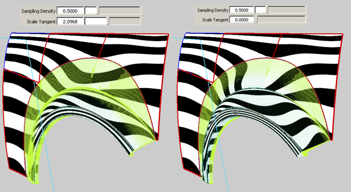
Scale Tangent
Scales the length of the tangency at constraints. A value of zero gives tangent continuity, and as you increase this number, the “length” of the tangency increases. This value can be adjusted to non-integer values as well.
Sampling and Diagnostics
The overall intent of the controls in this section is to help control the quality and performance of Transformer Rig modifications.
Some error conditions stop the deformation from proceeding. When a deformation cannot be applied, the outlines of target geometry are drawn with dotted lines.
Stress Exceeds Threshold: This error condition is triggered if there is too much stress in the shape modification, typically due to conflicting modifiers and constraints simultaneously forcing the surface to move and stay put. Red arrows point to the samples with too much stress. You can correct the condition by rearranging modifiers and constraints so that they do not conflict.
Too many samples. This error condition is triggered when the Sampling Density creates too many sample points. Sample points can be viewed by turning on the Draw Modifier Sampling check box. To correct the error, either increase the Maximum Number of Samples field, or reduce the number of samples by decreasing the Sampling Density field or eliminating unnecessary modifiers and constraints.
Draw Modifier Sampling
If this box is checked, this value enables you to visualize the sampling of the modifiers and constraints.
Draw Clamp Visualization
If this box is checked, the Transformer Rig tool draws a visualization to improve understanding of the clamp regions.
Sampling Density
Determines the number of samples on the modifier and constraint geometry. These sample points guide the shape modeling process. As the number of sample points increases, so does the accuracy of the warp — the time it takes to perform the modification also increases.
Number of Samples
Shows the number of samples used to compute a shape modification.
Maximum Number of Samples
Allows control of the maximum number of samples used to compute a shape modification. You can increase this number if you must, but remember that shape modifications could take longer.
Status
Indicates the status of shape modification, including failure modes.
Control Options
Auto Update
If checked, any changes in any field in the control box lead to an automatic update of the model display. If Auto Update is not checked, click the Go button in the active window to update the display after any changes. Normally, if you have a very large model that takes a long time to update, leave the Auto Update box unchecked.
Go button

If Auto Update is on, the Go button is not shown. Any changes to the rig (parameters or constructors) cause the history to re-evaluate automatically and immediately.
If Auto Update is off, the Go button is displayed. Any changes to the rig cause the Go button to be enabled, and when you click Go, the re-evaluation occurs. History itself exists the moment you enter the tool — not clicking the Go button does not change this, and you do not lose history by prematurely leaving the tool.
While a recalculation is occurring, a progress bar is shown on screen. If you feel the evaluation is taking longer than you care to wait, you can cancel it by pressing the Esc.
Mesh Output
If checked, NURBS targets are tessellated and output as mesh surfaces.
Apply Trim-Shrink to Output
When checked, the associated output surfaces are trim-shrunk before any shape change. This option changes only the output surfaces, not the inputs. You may find a performance improvement and better results using this option.
Transformer Rig workflows
Transformer Rig general workflow
Open the Transformer Rig Toolbox by clicking the Transformer Rig tool icon
in the Object Edit palette.The Transformer Rig Toolbox opens.
Select the target geometry, then click Accept Targets.
Choose either the Add Free Modifiers or Add Predefined Modifiers tool. Select the modifier geometry, then click Accept Modifiers.
For further information about adding modifiers, see the individual tool descriptions.
Optionally
Select constraints
Select clampers if the clamp visualization still shows problems. For more information, see Add clampers.
Click Go in the lower right corner of the screen. Leave the tool by choosing a continuous tool.
Now you can modify the targets using common Alias tools like transform or transform CV on the modifier geometry.
When you have finished modifying the geometry, Commit to the modification, or Revert to start over. For more information, see Commit and Revert.
Note: Diagnostic shading is lost for deformed objects with the transformer rig. When using the transformer rig tools, any objects you request to be deformed lose their diagnostic shading. The software creates new surfaces for these objects. Whenever a tool creates new surfaces, these surfaces do not display diagnostic shading. Click diagnostic shading in the Control Panel to reapply it to the objects.
The geometry tagged as targets in the rig now shows up in dark green, which shows it has construction history. To modify the rig (such as adding or removing modifier geometry, targets, and constraints), query edit any target geometry to re-enter the tool.
If the transformer rig setup has any problems, the output geometry is shown with dashed lines to indicate that it has errors that must be corrected. For tips on how to correct problems, see Trouble Shooting.
Understanding a chain of curves
In several tools in Alias, a series of curves can be treated and considered as a single curve, if they are positionally continuous (one curve ends, and the next one starts at the same point). In the Transformer Rig, you can select a chain of curves to serve as a single modifier. This chain of curves can serve as a constraint, predefined modifier, or free modifier.
Set up a Transformer Rig
Click the Transformer Rig icon to open the Transformer Rig toolbox.
First, the Transformer Rig expects you to specify the initial set of target geometry.
Pick all the geometry that should be modified, and ensure that geometry that shouldn’t change is not included.
When you're satisfied with your selection, click Accept Targets.
Remember: you can always add to or remove from the target geometry set later.
Next, you are prompted to add modifiers. In a Transformer Rig, there must be at least one modifier geometry.
Click the modifier icon (either Add Free Modifiers or Add Predefined Modifiers) that suits your needs.
Select the geometry that will serve as a modifier.
Click Accept Modifiers when you are satisfied with your selection of modifier geometry.
Next, add geometry that will constrain the changes to the model. Click the Add Constraints icon.
At this point, you may want to edit the pick mask before selecting curves to use as constraints.
Instead of using the Marking Menu, click on the Show Pick Mask icon to open the Transformer Rig Pick Mask: Add Target Mode window to modify the pick mask.
You may want to turn off options for entity types that you don’t want to accidentally pick.
Close the window.
Click or click-drag to select the constraint geometry.
Click Accept Constraints when you are satisfied with your selection.
To finish, click Go.
Use a Transformer Rig to modify shapes
To use the Transformer Rig, you leave the Transformer Rig toolbox and change the shape of the model by manipulating the rig with the standard Alias transform tools.
Leave the Transformer Rig toolbox by choosing Pick > Object.
The color highlights disappear when you leave the tool. Also notice that the geometry selected as targets now has history.
Pick the modifier geometry.
Use one of the Transform tools (Move, Scale, Rotate, Non-p scale) on the modifier geometry to achieve the desired shape.
Through Transformer Rig history, the target geometry updates automatically when you change the modifier geometry. You can also change modifier control vertices, and attributes such as degree and number of spans.
Change Transformer Rigs
Modify a Transformer Rig by using Query edit on any one of the target geometries.
After you have created a Transformer Rig and exited the Transformer Rig toolbox, you can still return to the toolbox and make modifications.
In the Object Edit tool palette, select the Query Edit tool
 .
.Use the
 to click on any one of the target geometries.
The Transformer Rig toolbox plus all the color highlights reappear to show that you have returned to the Transformer Rig toolbox.
To remove a target surface from the rig, place the cursor over the yellow-green highlight, and click with the
, or choose the Remove from Rig tool.A contextual menu appears at the cursor. Choose Remove from the menu.
The corresponding yellow-green highlight is removed, and the surface returns to its pre-transformer rig shape.
To add new target geometry, click either the Add Flexible Targets (if the target is permitted to have its shape modified) or Add Rigid Targets (if its shape should not change, even though its placement might) icon.
Use the
to select the surface to be assigned as a target.Click Accept to add the new target surface to the rig.
The shape of the surface will follow the modifier surface, and yellow-green highlights appear on the surface.
Use rigid targets with Transformer Rigs
Rigid targets are free to translate and/or rotate according to the modifications you have made. However, they are not to change shape at all: hence the name "rigid".
Click the Transformer Rig icon to open the toolbox.
Click the Transformer Rig tool. You are prompted to select geometry.
Pick the surfaces to be modified.
Click Accept Targets. The selected surfaces become flexible targets.
You are prompted to add modifiers.
Choose the tool (either Free or Predefined) and select the geometry to serve as modifiers, then click Accept Modifiers.
You are prompted to add Flexible or Rigid targets.
Click the Add Rigid Targets icon.
Pick the surfaces that should change position or orientation, but not change shape.
Click Accept Targets after selecting appropriate surfaces.
The rigid targets are now highlighted green, with the word Rigid on top of them. You can modify the attributes of the target by clicking it with the
to open this menu: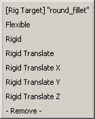
This menu enables you to switch a target from rigid to flexible, and vice-versa. You can also prevent rotation of the target by choosing Rigid Translate, or constrain it further by choosing one translation axis.
Now add Constraints if they are required. Click the AddConstraints icon.
Pick the appropriate geometry.
Click Accept Constraints to add the geometry as constraints.
Click Go to finish
In the Pick tool palette, select the Object tool
 to leave the Transformer Rig toolbox, and select the modifier surfaces.
In the Transform tool palette, select the Move took
 to reposition the modifier surfaces.
Notice the rest of the surfaces are modified accordingly. Specifically, notice that the rigid target surfaces retain their shape.
Use predefined modifiers with Transformer Rigs
Predefined modifiers are pairs of geometry. The first one indicates where the target geometry was, and the second indicates where the target geometry is supposed to go.
Click the Transformer Rig icon to open the toolbox.
Select the target geometry.
Click Accept.
Now click Add Predefined Modifiers to start adding before-and-after pairs of modifiers.
First click on the geometry that is in the “Before” or “From”position, location, or shape.
Click Accept to continue.
Select the corresponding geometry that is in the “After” or “To” position, location, or shape.
Click Accept to finish.
To add more pairs of modifiers, click Add Pre-Defined Modifiers again and follow steps 4 through 7.
Add a clamp to surfaces in Transformer Rigs
The Transformer Rig provides visual feedback about what is outside the region of modification. Red dots show regions that are clamped (will not change), while pale yellow dots show regions that are free to move.
The Transformer Rig uses the modifiers and constraints to make an educated guess at what is outside the region of modification, but sometimes it needs help to determine this correctly.
To provide the Transformer Rig with a hint that a particular part of the surface is to be held fast, add a clamp point. Clamp points can only be added if there are targets and constraints already applied to the Rig.
Choose the Add Clampers tool to start.
Click on the edge of the surface that should not be modified by the Transformer Rig.
A pink indicator appears where you click to show that a clamp point has been established.
If you are clamping an area that has inadvertently moved, you will see that it snaps back to its original, and proper, position.
The visualization also updates to show that the Transformer Rig has understood to hold fast the selected area of surface.
Add more clamp points, if required, by repeating the process.
Troubleshooting Transformer Rigs
If, after setting up a Transformer Rig and clicking Go, the surfaces do not update as expected,
Check to see if the rig was set up properly.
- Check to see if target surfaces are drawn using dashed lines: that is how the tool indicates there is an error in the calculations.
- The first setup might not be the best: try modifying the rig and recalculate to see if the results are improved.
Try the options in the current selected Fitting Method.
increasing the values in the options tends to give you a more accurate result which takes longer to compute
Try the other Fitting Method.
Each case is different — it all depends on the geometry and the intent. As you gain experience using the tool, you will develop a better feel for which method works best.
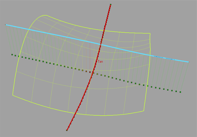
Draw Correspondence gives visual feedback as to whether there are conflicts in the rig, as a result of interfering modifiers and constraints. The visualization is green where there is no conflict, and graduates from green to yellow to red to show regions of conflict. This is a good diagnostic tool when the shape modification behaves wildly.
In the following image, the modifier and the constraint intersect. Notice that close to the intersection point, the visualization turns from green to yellow to red, to indicate that there is a conflict.
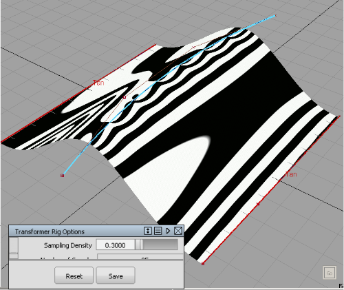
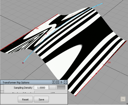
The Sampling Density field controls quality and speed. A low value results in faster updates, but may introduce quality problems. A higher value results in a more faithful shape modification, but increases the update time. The following images show how artifacts are introduced when sampling is too low, and how they can be avoided with a higher sampling rate.
Several factors may contribute to undesirable shape artifacts. They have been discussed above, and may include inappropriate NURBS fitting, low sampling density, and conflicts between constraints,modifiers, and clampers. To rule out inappropriate NURBS fitting, try toggling Mesh Output and seeing whether artifacts are affected. To rule out sampling density, try a higher sampling density setting.
After setting up a Lattice Rig, the rig may be partially or totally locked.
Transformer Rigs best practices
When setting up a Transformer Rig, we recommend:
Fitting Method set to Explicit (in the option window).
If working with a large file with many surfaces, Adaptive Fitting Method requires tighter calculations and will slow down the rigging process (which may not be necessary at this point).
When setting up modifiers:
Curves, surfaces and construction points can be used.
If you want to use a trimmed boundary edge or a surface boundary for a modifier (free or predefined), first duplicate the boundaries and use the duplicates instead.
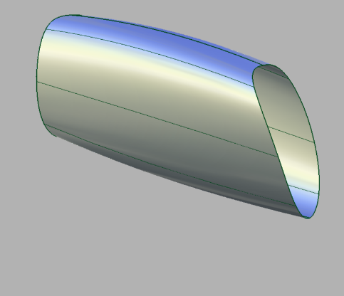
In this example, we want to stretch this shape by dragging the trimmed boundary.
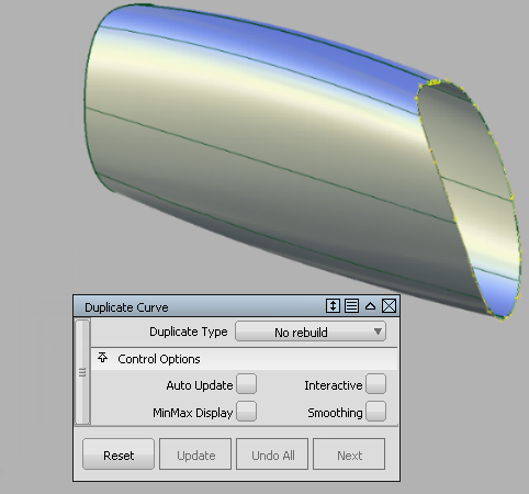
First, using Duplicate Curve, we make a copy of the trim boundary.
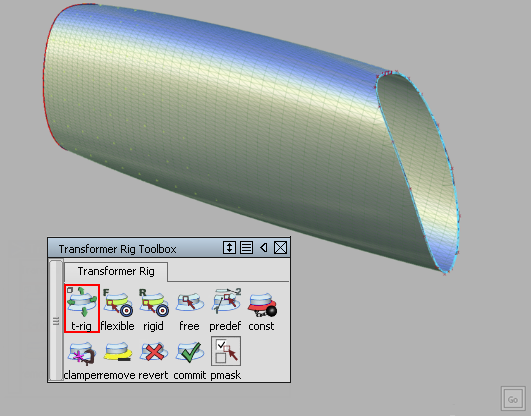
Assign the duplicated curve as the Free Modifier.

Pull the duplicated curve to stretch the shape.
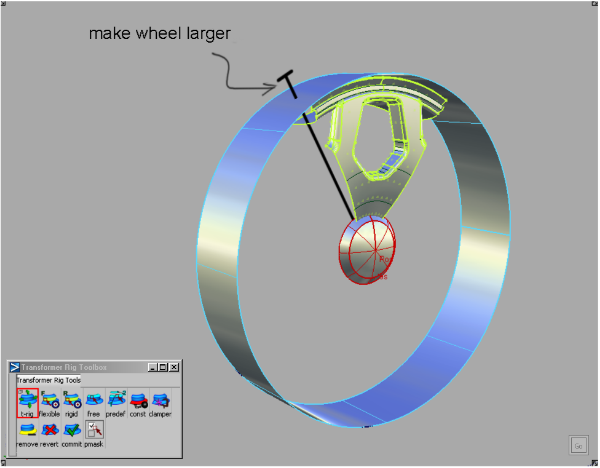
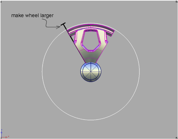
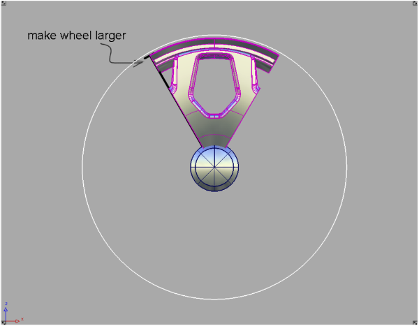
Sometimes transformations need to preserve an overall form: for example, circular shapes and planar elements.
Examples of these are wheel deformations (where radial symmetry must be preserved) and wheel well deformation (where planarity of the well must be kept).
The general principle is that, in these cases, modifiers have to be overbuilt. For example, for wheel spoke deformations, the deformer should be a cylinder, not just an arc.
For a wheel well deformation, the modifier should be a plane that is considerably larger than the wheel well.
The modifier should also be close to the target surface.
About the Transformer Rig
Compared to the Lattice Rig, the Transformer Rig tool is used for more controlled shape modifications driven by specific features of the model.
Custom modifiers and constraints
The Transformer Rig enables you to create custom modifiers specific to the model being changed. This provides tighter control of the surface modification.
The Transformer Rig also enables you to constrain parts of the selected target geometry. You can select real geometry to constrain the modifications, which makes the entire warp result more precise, and enables you to make finer-grained changes.
Flexibility
The Transformer Rig offers an additional NURBS fitting objective called Accurate.
Glossary of terms
Constraints
To secure parts of the target geometry to prevent shape modifications, use constraints. Dynamic shape modeling analyzes the transformer rig and assumes that the constraints delimit a region of interest (ROI). Parts of the targets that lie outside of the ROI are clamped (they will not move). The estimate of the region of interest, however, is not always correct. If there are inaccuracies in the ROI, use clampers.
Clampers
Clampers are hints you place outside the intended region of interest to help the tool understand the desired ROI. Clampers help ensure that modifications don't happen outside the ROI.
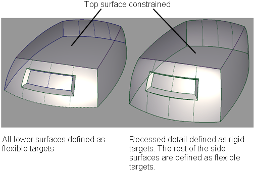
Rigid targets
In some cases, there are geometries or objects within the target geometry that should keep their shape. Usually these are parts like buttons, door handles, and lights. These rigid targets are moved embedded in the flexible targets, but they do not lose their shape during the warp. Making a target rigid helps preserve the shapes of the parts while allowing them to move with the surface. Imagine grommets moving on a rubber tarp that is stretched to cover a load: the grommets remain the same shape and size on the flexible surface of the tarp.