 Align
Align
Aligns a curve or surface edge to another curve, or surface edge as well as aligning an edge to the interior of a surface.
The Align tool moves or reshapes a curve or surface to achieve positional, tangent, or G2 curvature continuity with another curve or surface, and it offers G3 curvature continuity.
Access this tool from the Object Edit tool palette:
Align Options
The word "curvature", used on its own, refers to both G2 and G3 curvature.
Continuity
Continuity level between the aligned geometry: G0 Position, G1 Tangent, G2 Curvature, or G3 Curvature.
Lock Position Row
For G1, G2, and G3 continuity alignments, locks the position of the aligned edge CVs to prevent them from moving as you change options.
Alignment Type
- Edge – This option is the default and provides alignments for all surfaces when a vector constraint is not used. This includes the alignment of a surface to a surface edge, isoparm, or curve-on-surface (CoS).
- Project – This option aligns an edge to a surface by using a projection vector (along the current view by default). It is not necessary to have a curve-on-surface already on the surface to align to it. The curve-on-surface is created automatically.
- U/V – This option only appears when aligning a curve to a surface.
The curve is aligned to either the U or V direction of the surface.
- Vector – This option only appears when aligning a curve to a surface.
The tangent and curvature alignment is defined by the tangent plane to the surface at the point of contact, and the direction of the vector specified through Vector Options. That is, the tangent and curvature CVs on the curve are only allowed to move in the direction of the vector. This is the equivalent to creating a curve-on-surface on the surface, and aligning the free curve to it.
If the vector is set to View, the shape of the curve in the given view remains the same through the alignment, while maintaining the desired level of continuity with the surface.
Vector
This checkbox is only available when aligning a surface to another surface with Alignment Type set to Edge and Continuity set to G1 Tangent or G2 Curvature.
When Vector is checked on, positional continuity is achieved first, then the tangent and curvature CV rows are constrained to move along the selected vector. (See the Vector Options below.)
Tangent Balance
This option is only available when Continuity is set to G1 Tangent, G2 Curvature, or G3 Curvature and the following conditions apply:
- Both the Input and Master are surfaces
- You are aligning to a natural boundary (not a trim edge or curve-on-surface)
- Outer edges are both set to Edge Align
When Tangent Balance is checked on, the CVs of the tangent row are adjusted so that the ratio of the start and end tangent lengths on the Input surface matches that of the Master. If G2 Curvature or G3 Curvature is on, the same applies to the respective curvature row CVs (second and third rows from the edge). The inside CVs are also adjusted so that the Input’s hull (for the tangent and curvature rows) mimics the shape of the Master’s.
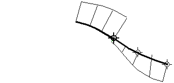
Tangent Balance is off.
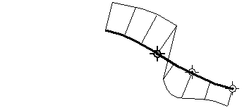
Tangent Balance is on. The hull shape of the Input reflect that of the Master.
The tangent and curvature lengths can be scaled in a proportional way so as not to change the shape of the Input surface, by using the Tangent Scale, Curvature Scale, and G3 Scale sliders (or corresponding manipulators). These sliders are only available when Tangent Balance is on, but retain their values if Tangent Balance is toggled off then on again.
Blending
This option applies to both Input curves and surfaces. It moves the inner rows of CVs to even out the modification in the Input. You can adjust the number of Extra CV Rows that get modified and the Blend factor to get the desired effect. The rows of CVs needed to maintain continuity are not touched.
Partial
The Partial checkbox is always off by default when a surface is aligned. Initially, the input surface’s edges are aligned to the full extent of the master’s edge. If Partial is turned on, the closest points on the master surface’s edge (or curve) are used.
The Partial Join manipulators are always displayed. Use the manipulators (or the Partials sliders) to control the extent. The Partial option applies when a surface edge is aligned to another surface edge, isoparm, curve-on-surface, or free curve
Partial is turned off automatically if the manipulators are dragged to the ends of the master’s edge. It is turned on automatically when the manipulators are dragged away from the ends.
Turning on Partial always resets the manipulators to the closest points on the master’s edge. Conversely, turning off Partial sets the manipulators to the ends of the master's edge.
Explicit Control
Checking on this option gives you access to the Explicit Control Settings where you can adjust the degree and number of spans for the Input. These settings only appear once both the Input and Master geometries have been selected. The degree and span settings initially correspond to those of the Input curve or surface.
Increasing the degree or adding spans can provide greater flexibility for the curve or surface to align to continuity, or create a more subtle blend. Explicit Control is checked on by default.
If Explicit Control is not checked, the alignment will first raise the degree of the Input to match that of the Master, before attempting to insert spans to achieve continuity.
Shrink to Fit
Ensures the projection happens when the slave surface overlaps the master surface. When Shrink to Fit is selected, the position row is compressed to fit onto the master surface.
No COS
When selected, does a projection align without creating a curve-on-surface. Continuity Check is disabled without a curve-on-surface.
Position Influence
This slider only appears when Alignment Type is set to Edge and Vector is off.
When Position influence is set to 0.0 (default), the alignment process attempts to maintain the parameterization of the Input surface. This alignment will not cause any CV movement provided the fit is already within the Curve Fit Distance tolerance. If the edge needs to be refit, there may be minimal CV movement.
When Position Influence is set to 1.0, the alignment attempts to match the parameterization of the Input surface to the parameterization of the Master as closely as possible. This alignment has more freedom to produce a closer fit (better continuity), but can cause the lateral spacing of position, tangent, and curvature CVs on the Input to change. However, tangent and curvature lengths are not affected by Position Influence.
The slider provides for incremental interpolation between maintaining parameterization on the Input and providing continuity with the Master.
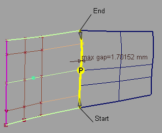
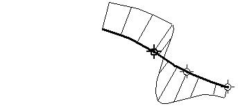
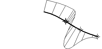
Position Influence = 0. Positional continuity not achieved.
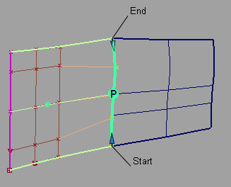
Position Influence = 1.0. Positional continuity achieved.
Blending Options
Extra CV Rows
Number of CV rows affected by the blending. These rows are located beyond the rows of CVs needed to maintain continuity, which are not touched.
Blend factor
The degree to which the influence of the alignment decreases or increases as it moves out to the extra CV rows. (This option is only available if Extra CV Rows is greater than zero.)
A positive value indicates that the influence decreases exponentially. The higher the value, the more rapidly the influence drops.
A zero value indicates no drop in influence; the change is constant row by row.
A negative value indicates that the influence increases exponentially. The higher the absolute value, the more rapidly the influence increases.
Vector Options
X,Y, Z
Select one of these options to specify a vector along that axis.
View
Select this option to specify a vector normal to the current view. The vector is not drawn in the view windows.
If the current view is changed, click Refresh Vector to update the vector.
Picked
Selecting this option lets you specify the name of an existing vector in the Picked Vector field, or pick the vector in the view.
Normal
The alignment is done by moving the CVs along the surface normals instead of using a single vector direction.
Refresh View Vector
This button only appears if View is selected. Click it to update the vector if the view has been modified.
Retain Vector
Click this button to create a vector construction object in the view windows. If you do not click this button, the tool uses the vector direction you specified, but you are not able to see and re-use the vector.
Additional information
Every Align workflow that requires specifying a direction through the Vector Options uses the X, Y, and Z axes from the construction plane, if one is set.
The following rules apply:
- Projections always respect the current coordinate system.
- If a projection was made in one set of coordinates (construction plane), and is later query-edited in a different one, the Refresh Vector button in the control window can be clicked to update the projection.
- If a construction plane is moved after creating a projection, nothing happens automatically. If the surface is query-edited later, the Refresh Vector button lets you refresh the projection.
Projection Align along Z in global coordinate system
After setting a construction plane and clicking Refresh Vector, the projection is updated.
Explicit Control Settings
U Degree
Degree of the Input surface in the U direction.
V Degree
Degree of the Input surface in the V direction.
Degree
Degree of the Input curve.
U Spans
Number of spans on the Input surface in the U direction.
V Spans
Number of spans on the Input surface in the V direction.
Spans
Number of spans on the Input curve.
Outer Edge
The following section only appears when Alignment Type is Edge, and Continuity is set to G1 Tangent, G2 Curvature, or G3 Curvature.
These options control the direction of the tangent (within the tangent plane) along the outer edges of the Input surface.
Align Start/End Together
When this box is checked, the setting for Start Align and End Align is kept the same.
Start Align/End Align
Edge Align – The edge is aligned to either the natural boundary or to a trimmed edge.
Skew – The edge is rotated by the specified Skew Angle while remaining in the tangent plane.
Click the label in the view window to toggle between Edge Align and Skew.
Start Skew Angle/End Skew Angle
The angle of rotation (in degrees) of the start or end outer edge.
These values can also be adjusted by using the small circle manipulators in the view windows.
The following section only appears when Continuity is set to G1 Tangent, G2 Curvature, or G3 Curvature.
These options control the length of the tangent or curvature. You can also use the tangent and/or curvature manipulators to adjust those values.
Tangent and Curvature CV Adjustment
Starting Tangent Scale/Ending Tangent Scale
These slider values let you adjust the true lengths of the tangents (in centimeters) along both edges of the Input surface.
Tangent Scale
This slider value lets you adjust the true length of the tangent (in centimeters) at the aligned end of the Input curve.
When aligning surfaces, if Tangent Balance is on, this slider lets you scale the tangent lengths in a proportional way, so as not to change the shape of the surface. It retains its value if Tangent Balance is toggled off then on again.
AutoScale G2
If Continuity is set to G2 Curvature, this option adjusts the G2 curvature automatically while you scale the tangent. It attempts to maintain the same relative arm-lengths, that is, position-row to tangent-row versus tangent-row to G2 curvature-row, as in the unaligned surface (or curve).
If Continuity is set to G3 Curvature, this option adjusts both the G2 and G3 curvature automatically while you scale the tangent. It attempts to maintain the same relative arm-lengths as in the unaligned surface (or curve).
Starting Curvature Scale/Ending Curvature Scale
These slider values let you adjust the true G2 curvature lengths along both edges of the Input surface.
Curvature Scale
This slider value lets you adjust the true G2 curvature length at the aligned end of the Input curve.
When aligning surfaces, if Tangent Balance is on, this slider lets you scale the G2 curvature lengths in a proportional way, so as not to change the shape of the surface. It retains its value if Tangent Balance is toggled off then on again.
AutoScale G3
Adjusts the G3 Curvature automatically while you scale the G1 Tangent or G2 Curvature. It attempts to maintain the same relative arm-lengths, that is, tangent-row to G2 curvature-row versus G2 curvature-row to G3 curvature-row, as in the unaligned surface (or curve).
Starting G3 Scale / Ending G3 Scale
These slider let you adjust the true G3 curvature lengths along both edges of the Input surface.
G3 Scale
This slider lets you adjust the true G3 curvature length at the aligned end of the Input curve.
Partials
Start / End
These sliders values range from 0.0 to 1.0 and specify the percentage of the way that the start or end of the Input surface extends from the end of the Master surface (in parameter space).
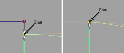
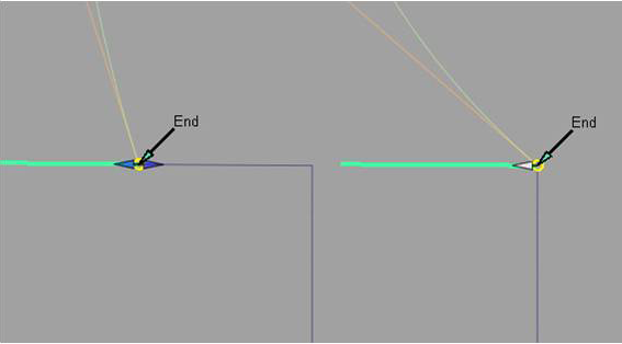
These values can also be adjusted by using the Partial slider manipulators along the boundary. The manipulators indicate they have been positioned at the full extent of the edge of the Master by displaying only the internal arrow. Double arrows indicate that the Input edge is not positioned at the full extent of the edge of the Master.
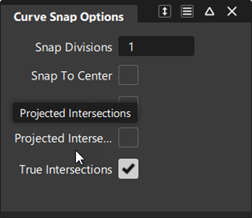
The Partial slider manipulators also snap to the options set in the Snap Options window (except for Snap to Center and Pivot).
Attach Point
This section applies to curve alignment only.
Attach Point
Point on the Master curve that the Input curve is aligned to. The slider value ranges from 0.0 to 1.0 and specifies the percentage of the way from the start of the Master curve.
Control Options
Create History
Saves the construction history of the alignment so you can edit the aligned objects or the tool options and the alignment automatically updates.
Auto Update
Automatically recalculates the alignment as you change the controls in the window.
Continuity Check
Adds a surface continuity locator to the aligned edge, giving a pass/fail indication on continuity and showing any discontinuities.
Continuity Check Type
When Continuity Check is on, you can choose to check for a specific level of continuity. Choose an option from the Continuity Check Type list, which includes G0 Position, G1 Tangent, G2 Curvature, and Tool Defined. Tool Defined checks for the continuity you specified for the alignment (with the Continuity option).
Enable Proxy Display
Check on this option to see the hull of the original input surface (surface being aligned) as a green proxy. This proxy helps you visualize how much the surface has changed during the Align operation.
If you click Accept to "store" the current state of the Align operation, the modified input surface becomes the new original surface. The proxy display updates to reflect this fact.
Diagnostic Feedback
When selected, the minimum and maximum Position, Tangent, Curvature, and Torsion values display, and the start and end Angle values display.
Buttons
Reset
Restores your saved settings. If you have not saved custom options, Reset restores the installed option settings.
Update
If Auto Update is off, click this button to recalculate the alignment and update the model in the view.
Revert
Click this button to cancel all changes to the Input and return it to its original shape, as if the tool was never invoked. All history is deleted.
Accept/Restore
Each time the Accept button is clicked, a configuration of the tool and the current Input geometry is saved.
The Restore button is only available when the Accept button has been clicked at least once. Each time the Accept button is used, the state is stored, and can be retrieved by using the Restore button. This way, it is possible to append a series of alignment operations.
Using the manipulators
The manipulators appear as small arrows or double arrows, except for Skew which is an arc with a small circle. Once the manipulator is engaged by clicking the arrow or circle, mouse contact is not required to make further modifications.
The following values can be adjusted directly through manipulators:
- Position of Attach Point on curves.
- Tangent length, G2 curvature, and G3 curvature length along the outer edges, when Tangent Balance is off. A center manipulator lets you keep the existing length ratio between both ends (akin to “sliding” the hull).
- Skew angles on the outer edges.
- Tangent scale, curvature scale, and G3 scale for surface alignment when Tangent Balance is on, so that all tangent and curvature lengths on the input surface are scaled proportionally, to maintain the surface shape.
- Partial join manipulators. These change from double to single arrows when snapping to the edge of the Master surface.
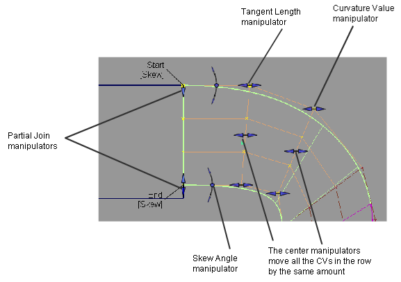
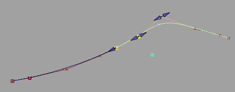
Surface alignment manipulators
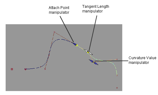
Curve alignment manipulators
Align tool workflows
In the following workflows, the word "curvature", used on its own, refers to both G2 and G3 curvature.
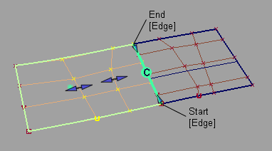
Align surface edges
This aligns one surface to one or more surface edges, trimmed edges, curves, curves-on-surface, or isoparametric curves.
Shift-select the Align tool.
Note that Alignment Type is set to Edge by default.
Click the edge of the surface you want to align (the Input).
Sequentially click the edges of the surfaces you want to align to (the Primaries). These can also be curves, isoparms, curves-on-surface, or trimmed edges.
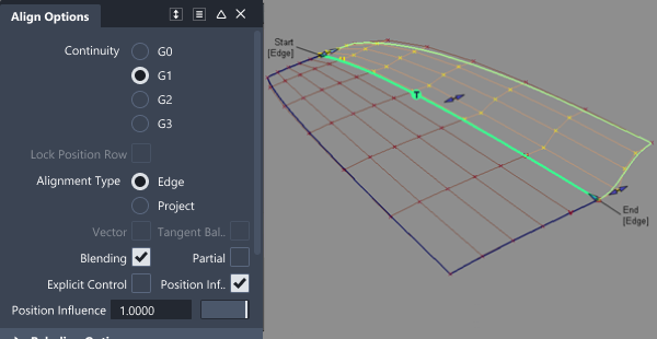
Align the edges with the Position Influence slider to help achieve positional continuity if needed.
When the value of the slider is 0.0, the surfaces being aligned keep their parameterization intact. As the slider is moved to 1.0, it attempts to match the parameterization of the Primary surfaces, which results in a better fit.
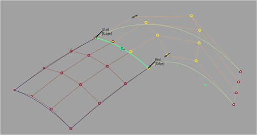
Set the continuity level to G1 Tangent, G2 Curvature, or G3 Curvature in the Continuity section of the option window, if desired.
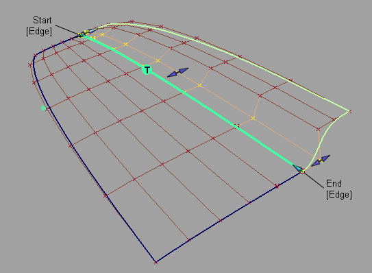
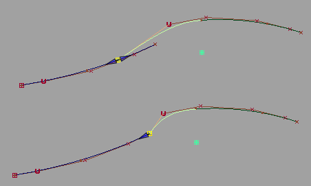
Manipulator arrows allow direct manipulation of the tangent and curvature lengths.
The arrows on the outside of the surface provide independent scaling of the tangent and curvature lengths on each side. The arrow in the middle of the tangent or curvature rows moves all the CVs in that row by the same amount.
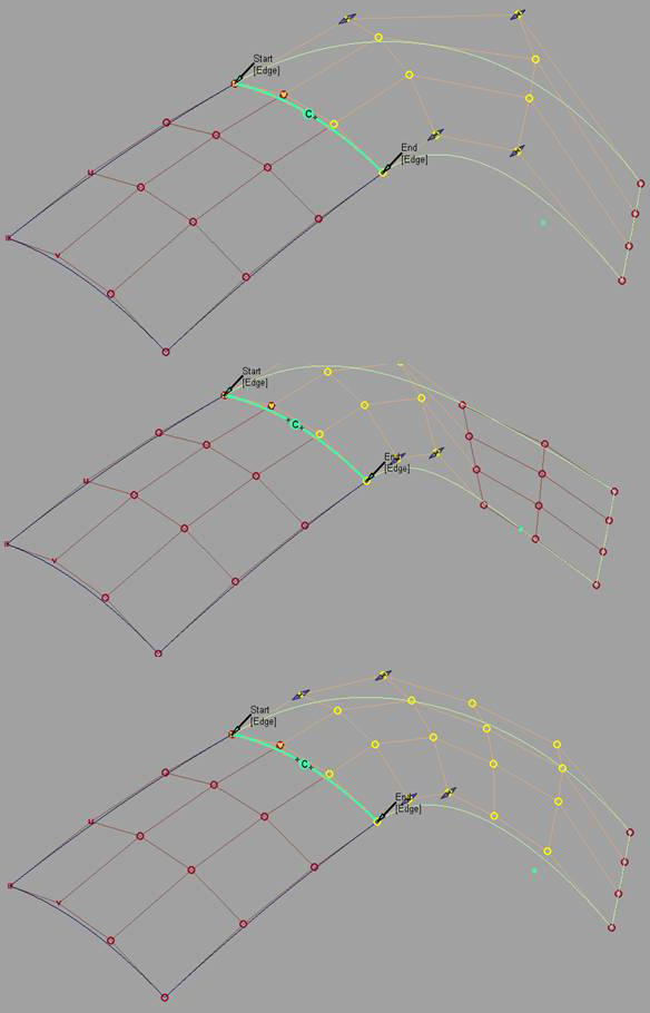
If the requested continuity is not achieved, try one or more of the following:
Adjust the Position Influence slider. It will help line up the CVs along the boundary.
Turn on Tangent Balance to try and match the hull shape of the Primary surface, or adjust the tangent lengths along the edges with the manipulators.
Turn off Explicit Control. This will automatically set the degree of the Input to that of the Primary in the direction of the alignment. You can also manually adjust the degree and number of spans through the option window.
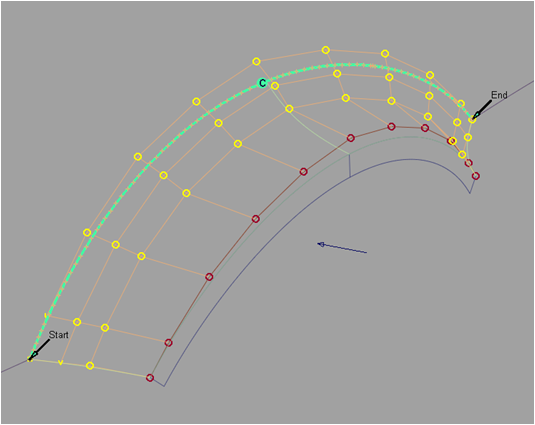
Here Position Influence has been set to 1.0 and Explicit Control turned off to match the degrees. Notice how the CVs now line up perfectly across the boundary.
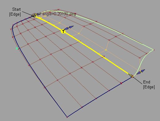
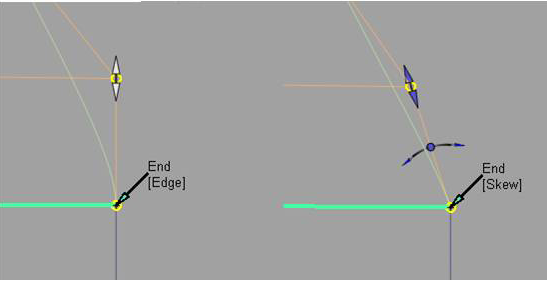
Change the outside edge alignment by clicking the Edge label to toggle between Skew or Edge Align. Or set Start Align and End Align in the Outer Edge section of the option window.
When Skew is selected, a rotational manipulator becomes visible which allows direct modification of the skew angle. You can also specify a specific Skew Angle value in the option window.
When Edge Align is selected and you are aligning to a natural surface boundary, you can turn on Tangent Balance to adjust the CVs on the tangent row so that the tangent lengths of the Input surface match those of the Primary. The same applies to the curvature row CVs if G2 Curvature is on, and to the next row of CVs if G3 Curvature is on.
 Note: Undo ('Ctrl' + 'Z') can be applied to any manipulator modifications.
Partially align two surfaces
Shift-select the Align tool.
In the Align Options, turn on Partial.
Click the edge of the surface you want to align.
Click the edge of the surface you are aligning to (Primary).
The first surface is aligned to the closest points on the second surface.
Modify the location of the endpoints with the Partial manipulators.
The Partial manipulators will change from a double sided arrow to a single arrow when they snap to the end of the Primary surface.
You can also use the Start and End sliders in the option window.
Blend an alignment
Blending extends the influence of the blend further into the surface or curve.
After an alignment has been created, turn on Blending in the Align Options to add blending.
Select how many Extra CV Rows the blend will apply to.
Modify the Blend factor to provide more or less influence from the original alignment type.
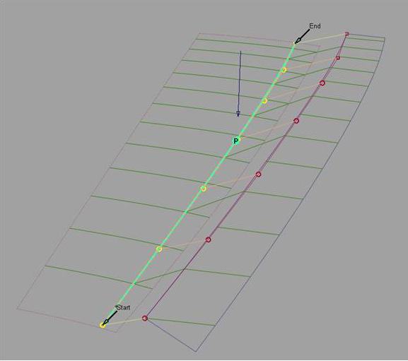
Two rows beyond the tangent row are affected by the Blend factor.
Note: Blending can be applied to a positional alignment as well to create a smooth distribution of CVs from the alignment edge.
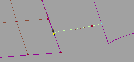
Align using a directional constraint (Vector alignment)
Once a positional alignment has been established, the tangent and curvature rows can be aligned with a vector (directional) constraint.
Establish the edge positional alignment. (See steps 1-4 of Align surface edges).
If needed, add additional CVs with the Explicit Control sliders.
Set Continuity to G1 Tangent, G2 Curvature, or G3 Curvature.
Click on the Vector checkbox to turn the option on.
The Vector Options section appears in the option window.
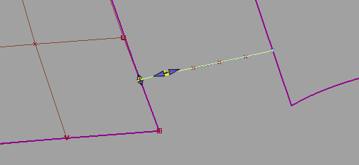
Do one of the following:
- Choose X,Y, or Z as the vector direction
- Choose Picked and select an existing vector
- Choose View to use the direction of the current view as the vector direction.
- Choose Normal to use the surface normals as the vector direction. The direction varies according to the position of the CV on the surface.
The tangent and/or curvature CVs are modified along the vector to create the required level of tangency or curvature.
If the alignment cannot be maintained with your choice of directional constraint, the edges of the aligned surface appear as dashed lines.
Note: Sequential alignments can be applied by clicking the Accept button, and removed by clicking the Restore button, at the bottom of the Align option window.
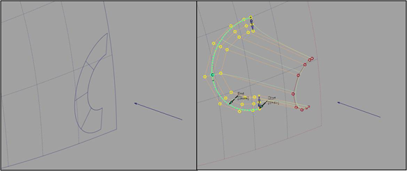
Align by projecting an edge onto a surface (Projection alignment)
A surface can be aligned to the inside of one or more surfaces by projecting the edge along a vector down to the Primary surfaces.
Shift-select the Align tool.
In the Alignment Options, set the Alignment Type to Project.
Select the edge to align.
The Vector Options section appears.
Do one of the following:
- Choose X,Y, or Z as the vector direction
- Choose Picked and select an existing vector
- Choose View to use the direction of the current view as the vector direction
- Choose Normal to use the Primary surface's normals as the projection direction, instead of using a single vector.
Select the surfaces to align to (Primaries).
The edge is projected along the defined vector onto the Primary surfaces. A curve-on-surface is created as well, and can be used later for trimming the Primary surfaces.
 Note: If the edge of the surface being aligned falls outside the boundaries of the Primary surfaces, the alignment cannot be completed successfully.Note: If the alignment cannot be created using your choice of projection direction, the edges of the aligned surface appear as dashed lines.Tip: Modification of the projected edge can be made after the alignment by modifying the CVs with Control Panel > Transform CV.
Align a surface edge to an entire curve
This aligns the length of the surface edge to the length of the curve.
Shift-select the Align tool.
Click the edge of the surface you want to align.
Click the primary curve.
In the Align Options, turn on Partial. This lets you align to only a portion of the primary curve.
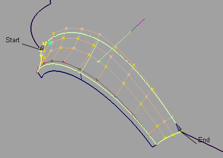
Align a curve end to a surface edge, isoparm, or curve-on-surface
This aligns the end of the curve to the end of the surface curve.
Shift-select the Align tool.
Click the curve close to the end you want to align. Click the surface edge, isoparametric curve, or curve-on-surface at the point you wish to align to.
Set Continuity to G1 Tangent, G2 Curvature, or G3 Curvature if desired.
The Alignment Type option becomes available. U/V is the default and aligns the free curve to the direction of the surface curve that you selected as the primary.
Set Alignment Type to Vector if you want to align a curve to the interior of a surface, without the need for a curve-on-surface.
The tangent and curvature alignment are then defined by the tangent plane to the surface at the point of contact, and the direction of the vector specified through Vector Options
Alignment Type = Vector: This is equivalent to creating a curve-on-surface on the surface, and aligning the free curve to it.
Align two curves
Shift-select the Align tool.
Click the first curve close to the end you want to align.
Click the second curve close to the end you want to align.
Set the continuity level by selecting G0 Position, G1 Tangent, G2 Curvature, or G3 Curvature in the Continuity section of the option window.
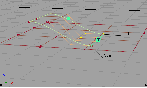
Manipulator arrows become available, allowing direct manipulation of the attach point location, as well as tangent and curvature scaling.
Modify the location of the Attach Point, Tangent Scale, Curvature Scale, or G3 Scale with the manipulators, or control window sliders.
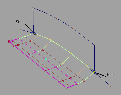
Aligning curves with positional continuity and modifying the Attach Point.
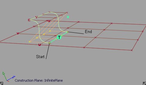
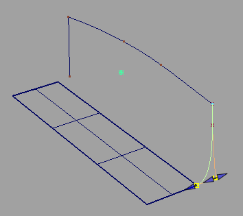
Aligning curves with G2 curvature continuity.
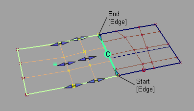
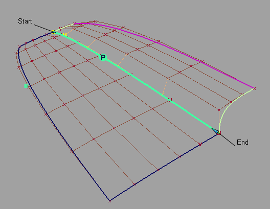
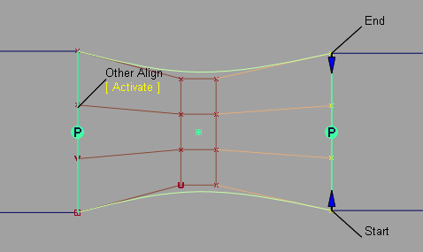
Align both ends of a curve or surface
When aligning both ends of a curve, or opposite edges of a surface:
Continuity settings at both ends are respected by all options, such as Blending.
Click the Activate label that appears under Other Align on the model, to switch between the two alignment operations.
Query Edit tool retrieves the construction history for both ends, and you can click the Activate label shown above to edit the alignment at both ends.
Note: When a curve or surface is aligned to two primaries, it has a single history item as seen with Windows > Information > History View. In this case, clicking the Revert button first reverts the active side (the one you last aligned). The history then applies only to the remaining side. Clicking Revert again deletes the history and returns the input geometry to its original shape.
About continuity
Continuity is a measure of how well two curves or surfaces “flow” into each other.
Why you would set continuity and curve degree
- To get more visual smoothness at intersections, increase the level of continuity.
- To increase the amount of flexibility available to achieve high levels of continuity, increase the curve degree.
Types of continuity
Continuity is a mathematical indication of the smoothness of the flow between two curves or surfaces.
The following lists the five types of continuity possible with Alias tools, G0 to G4. Note that G3 and G4 continuity are only available with blend curves.
Positional (G0)
The endpoints of the two curves meet exactly. Note that two curves that meet at any angle can still have positional continuity.
Tangent (G1)
Same as positional continuity, plus the end tangents match at the common endpoint. The two curves appear to be traveling in the same direction at the join, but they may still have very different apparent “speeds” (rate of change of the direction, also called curvature).
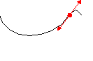
For example, in the illustration below, the two curves have the same tangent (the double-arrow line) at the join (the dot). But the curve to the left of the join has a slow (low) curvature at the join, while the curve to the right of the join has a fast (high) curvature at the join.
Curvature (G2)
Same as tangent continuity, plus the curvature of the two curves matches at the common endpoint. The two curves appear to have the same “speed” at the join.
Curvature with constant rate of change (G3)
Same as curvature (G2) continuity, plus the rate of change in the curvature matches between the curves.
Curvature with constant rate of change of the rate of change of the curvature (G4)
Same as G3 continuity, plus the rate of change of the rate of change of the curvature matches between the curves. This is the smoothest type of join.
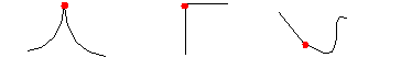
The concept of “rate of change of the rate of change” may be hard to conceptualize. Consider the following graphs:
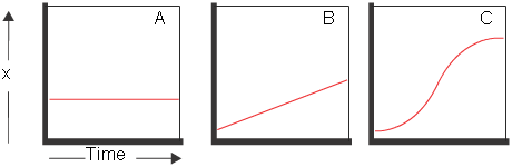
- In graph A on the left, the value of x does not change, so the rate of change of x is 0.
- In graph B in the middle, x has a constant rate of change, which we can calculate as the slope of the line.
- In graph C on the right, the rate of change is not constant: it is slow at first, then fast, then slow again. The rate at which the rate of change itself changes is the rate of change of the rate of change.