 Lattice Rig
The Lattice Rig is a box-shaped manipulator that enables global modifications to NURBS and subdivision models.The lattice box always starts in disengaged mode, and is initialized as a bounding box enclosing the selected geometry.
Overview
- The lattice can be modified and refined from its initial box shape without affecting the underlying targets (surfaces or meshes) as long as the lattice is disengaged. After developing a lattice that provides the shape and detail required, engage the lattice. Subsequent changes to the lattice will modify the targets.
- The lattice can be repeatedly engaged and disengaged for cumulative shaping modifications.
- The points on the lattice are not CVs — they are manipulator handles. They can be moved by using only the functions offered by the lattice rig tool.
- If there is an active construction plane, a new lattice respects the construction plane and aligns to it. Also, the manipulators of the lattice points independently respect the construction plane. That means that, no matter where or how the lattice is created, the manipulators respect the current active construction plane.Alias provides a box-shaped manipulator called a lattice to enable global modifications to the model.
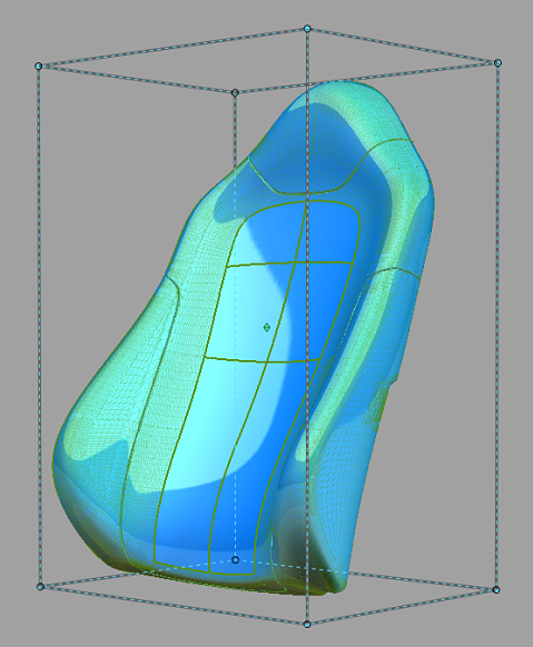
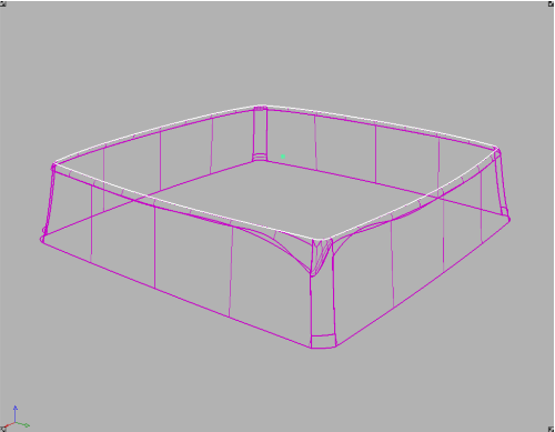
- The geometry being modified is represented by a proxy. A proxy is a lightweight wireframe representation of the targets being deformed by an engaged lattice. The proxy interactively updates while you modify the engaged lattice to show what the targets look like after deformation (see the following image). Meanwhile, the targets remain unchanged until you release the mouse button (when Auto Update option is ON) or when you click GO (when Auto Update is OFF).
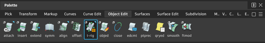
Access the Transform Rig from the Object Edit tool palette:
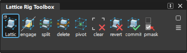
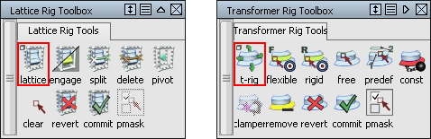
Lattice Rig toolbox
Selecting the Lattice Rig icon ![]() opens the toolbox:
opens the toolbox:
Lattice Rig option window
![]()
To open the option window, double-click or Shift-click the icon.
Toggle lattice engage state
![]()
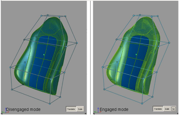
When the lattice is in disengaged mode, its lines are drawn as dashed lines, and changing the lattice does not change the target geometry. To engage the lattice, click the tool; to disengage, click the tool again. The tool works as a toggle between the two modes.
Split lattice edge
![]()
The split tool adds new lattice segments like a belt wrapped around the lattice box. The split tool is only accessible while in disengaged mode. To split an edge of the lattice, click this tool, and then click the edge that you want to split. The split is perpendicular to the edge you have selected.
To split the lattice right in the middle between two lattice points, press Ctrl while dragging the new split along the lattice. To confirm the location of the split, click Accept Split. When you have finished splitting the box, click the DONE button.
Delete lattice edge
![]()
This tool deletes the “belts” from the lattice box that were inserted.
Center lattice pivot
![]()
This tool allows you to center the lattice pivot. This pivot is the point about which the lattice points are scaled.
Lattice clear selection
![]()
This tool clears the selection for the lattice points.
Revert
![]()
When targets are added to the rig, they are duplicated. The shape modifications are performed with these duplicated geometry. To restore the original geometry and to delete the modified geometry and history, click Revert. Notice that the manipulated modifiers do not return to their status before the dynamic modeling.
Commit
![]()
Click Commit to confirm the dynamic shape modification and delete the original geometry and the history.
Show Pick Mask
![]()
This tool helps when selecting targets for use in the rig. It is only usable when you first enter the Lattice Rig.
Lattice Rig Options
Show Original Geometry
If checked, this box enables the display of geometry as it was before the Lattice Rig tool was applied. If unchecked, the current version of modified geometry is displayed. Use this feature to flip and compare “before” and “after” geometry.
Show All Geometry
If checked, this box enables the display of both the original and modified geometry.
NURBS Control
The fields in this section control the way the Lattice Rig tool modifies the NURBS target surfaces. Settings in this window have no effect on meshes that were selected as targets. If all targets are meshes, or if Mesh Output is set, this section of the option window is hidden.
Fitting Objective
The available methods are:
Hull Shape (Explicit) – Optimizes fitting for hull shape. This option allows for explicit control of minimum degree and spans. If the Boundary field is checked, the fitting is optimized for patch boundaries.
Accurate (Adaptive) – Optimizes fitting for accuracy. This determines the minimum number of spans necessary for an accurate representation of the modified shape.
The Fitting Effort option has been reorganized to a pull-down menu with Low, Medium, High, and Custom values. If Custom is selected, a slider can be used to set the value precisely.
Minimum Degree (u,v)
Specifies the minimum degree of resulting patches. If a patch target has degree less than the specified degree, its degree is raised to the specified degree. This has the result of making the math heavier, but in general the results of the shape modification are more accurate.
Minimum Spans (u,v)
Specifies the minimum number of spans in the U and V directions. If necessary, existing spans are subdivided. This has the result of making the math heavier, but in general the results of the shape deformation are more accurate.
Warp Control
The controls in this section can be used to adjust how the modifier and the constraints influence the target geometry.
Scale Tangent
Scales the length of the tangency at regions where the targets cross from outside to inside the lattice. A value of zero gives tangent continuity, and as you increase this number, the “length” of the tangency increases. This value can be adjusted to non-integer values as well.
Control Options
Auto Update
If checked, any changes in any field in the control box lead to an automatic update of the model display. If Auto Update is not checked, click the Go button in the active window to update the display after any changes. Normally, if you have a very large model that takes a long time to update, you should leave the Auto Update box unchecked. Auto Update is checked on by default.
Go button

If Auto Update is ON, the Go button is not shown. Any changes to the rig (options or constructors) causes the history to re-evaluate.
If Auto Update is OFF, the Go button is displayed. Any changes to the rig cause the Go button to be enabled, and when you click Go the re-evaluation occurs. History itself exists the moment you enter the tool — not clicking the Go button does not change this, and you do not lose history by prematurely leaving the tool.
Mesh Output
If checked, NURBS are tessellated and output as mesh surfaces.
Apply Trim-Shrink to Output
Turn on this option for trimmed surfaces if you want the associated output surfaces to be trim-shrunk before any shape change. This option changes only the output surfaces, not the inputs. You may find a performance improvement and better results using this option.
Work with the Lattice Rigs
In the Lattice Rig toolbox, the lattice is the manipulator to change geometry. Unlike with the Transformer Rig, the modification of the lattice and the target geometry both happen within the Lattice Rig tool.
Set up a Lattice Rig
Pick the surfaces that you want to modify.
Click the Lattice Rig icon to open the Lattice Rig toolbox.
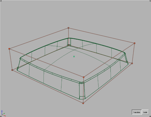
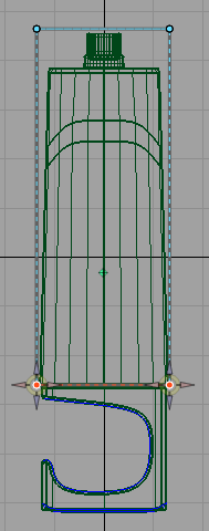
The toolbox of the Lattice Rig appears, and an initial lattice box is placed around the selected geometry. The lattice starts off being a simple box slightly larger than the target geometry.
Notice that the edges of the lattice are shown with dashed lines. This shows that it is "disengaged", and changes made to the lattice do not affect the target geometry.
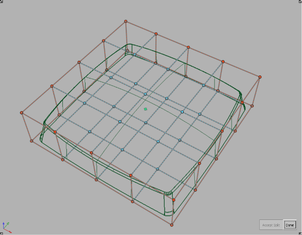
To add detail to the lattice, choose the Split Lattice Edge tool. Place the cursor over an edge, and click a mouse button. A set of green lines appears, which can be repositioned until you select either Accept Split or Cancel. If you are satisfied with the placement of the new edges, click Accept Split.
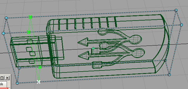
Repeat until there are sufficient number of points to best approximate the shape of the target geometry. Click Done when you are satisfied with the number of points.
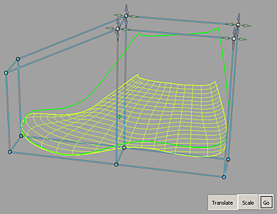
Next, start to move the points so the lattice better approximates the shape of the geometry.
You have a choice between translating (moving) or scaling the points.
Click-drag a box around a group of points to select them, or pick the points one at a time.
Points turn white when selected. Click Translate to enable the translate manipulators.
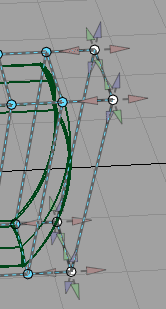
Notice the cones pointing out from the active points. These manipulators show the directions in which you can pull the points.
Pull manipulators and reselect points to shape the lattice to the geometry.
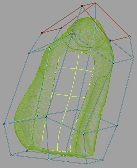
To scale points, click Scale. The manipulators change to the following:
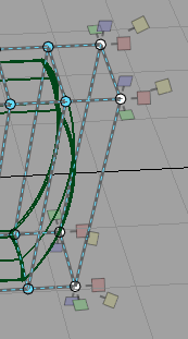
Pull manipulators and select points to scale the lattice.
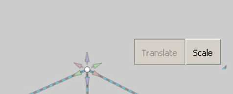
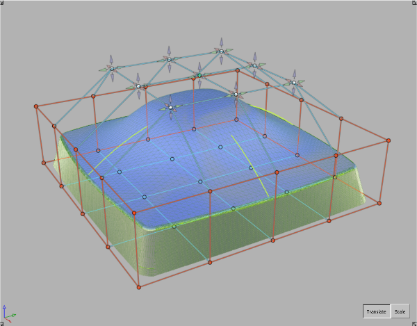
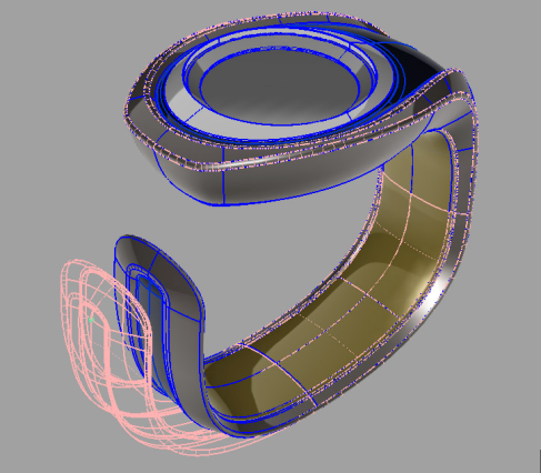
When you’re finished shaping the lattice, choose Toggle Lattice Engage State.
Notice that the lattice is now drawn with a solid color, and the target geometry is drawn in yellow-green. This indicates that the lattice is engaged, and further modifications to the lattice will change the target geometry.
Use the lattice to modify shapes
With the lattice engaged, pick a lattice point.
Click Translate, and move the lattice point.
Notice that the target geometry updates to reflect the change. If Auto Update is turned on, a lightweight proxy of the model is used for display purposes while the mouse button is held down, and the model updates when you release the mouse button. If Auto Update is OFF, the proxy is used until the Go button is clicked.
If you want to move a number of points, pick them, then move the picked points by using the manipulators on one of the points: the other points will follow.
- If you want to scale a point, click Scale, and pick and move the point.
- If you want to scale a number of points, pick them, then scale the picked points by using the manipulators on one of the points: the other points will follow. Note the location of the scale pivot. You can move it to an appropriate spot to affect the scaling operation.
Repeat the same workflow for the rest of the lattice points to reshape the geometry.
Lattice Rig workflows
How to use the Lattice Rig
Open the Lattice Rig toolbox by selecting the Lattice Rig Toolbox icon
.
The Lattice Rig Tools window opens.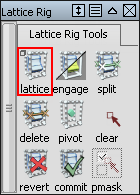
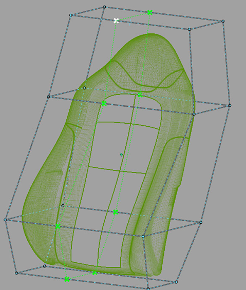
Select the target geometry, then click Accept Targets.
A basic lattice box appears around the geometry in disengaged mode.
Adjust the lattice box to the shape of your targets by splitting the box (which adds more points) and transforming lattice points using their handles.
When the lattice has the right shape, click the Toggle Lattice Engage State tool. The lattice box changes to solid lines in this mode.
All modifications made to the engaged lattice influence the shape of the targets enclosed by the lattice.
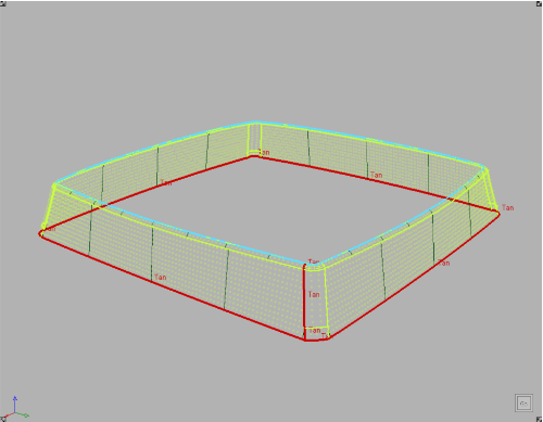
All the geometry not enclosed by the lattice are constrained. To show that these areas have been constrained, the lattice points and edges that intersect the geometry are shown in red.
Modify the lattice using the scale and translate manipulators.
Picking lattice points
Picking lattice points
| To do this... | Use this mouse button |
|---|---|
| Toggle pick |  |
| Exclusive pick |  |
| Remove pick |  |
To unpick all lattice points, use
- the and draw a pick box outside the lattice.
- the Clear Selection tool rather than using Pick > Nothing from the tool palette, which causes you to leave the Lattice Rig tool.
- the
Troubleshooting Lattice Rigs
If you are modifying trimmed surfaces, the part of the lattice that intersects with the discarded portions of the trimmed surfaces is locked. In this case, shrink the trim surface with the shrinkToTrim plug-in.
If you are modifying NURBS surfaces that protrude from the lattice, the outside portions may be modified. This is due to the global effects of NURBS fitting. If you want to reduce these effects, increase the number of spans. To eliminate them entirely, you may have to switch to Mesh Output.
When the Lattice Rig is applied to this surface, the two sides of the lattice are locked, with no obvious reasons.
If you turn on the CVs of the surface, you see that the surface is a trimmed surface, and the removed parts intersect with the lattice.
Shrinking the trim will fix this problem.
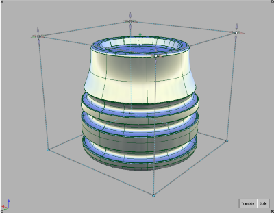
The Lattice rig may be too close to the surface. In these cases, move or scale the lattice away from the target geometry. In this example, the initial lattice is too close to the top of the target.
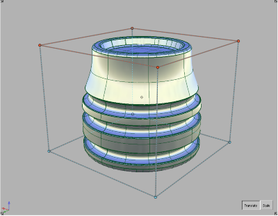
Translating the top of the lattice upwards solves the problem.
Refine the lattice using the Split Edge tool to give it more degrees of freedom.
Lattice Rigs best practices
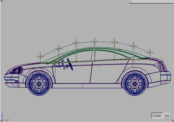
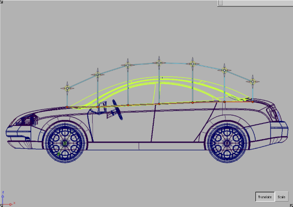
The Lattice Rig should be adapted to fit the geometry shape as best as possible. The closer the rig is to the shape of the geometry, the more controlled the results will be when the target geometry is modified.
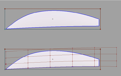
In this example, the initial lattice is based on the bounding box of the target surfaces. It does not match the shape of the target surfaces well, and is not going to be an effective lattice when deforming the greenhouse of this car.

In these next two illustrations, the lattice has been refined to follow the shape of the target surfaces better.
It is important that a modifier and a constraint do not cross or touch.
Otherwise, you are simultaneously telling the rig that a certain region must both move and remain stationary. The result is that points that were originally close will be pulled apart in unpredictable ways. In the following example, this can lead to crumpling or denting effects.
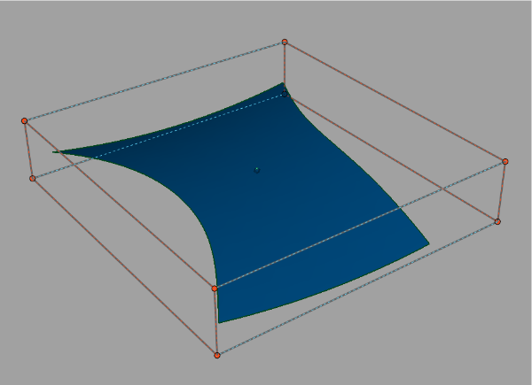
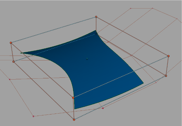
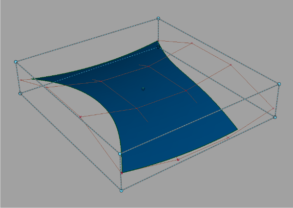
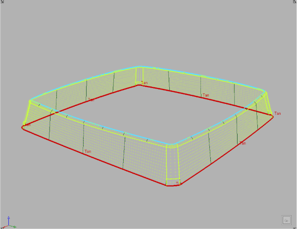
In this example, we want to stretch this box upwards. We define the top surface as the modifier, and the bottom curves as the constraints. The modifier and the constraints do not touch or interfere with each other.
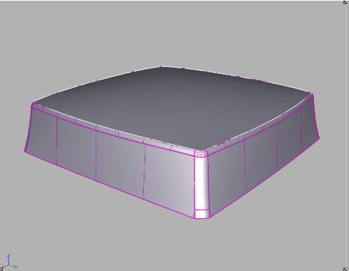
Therefore, the shape modification is successful, as shown here.
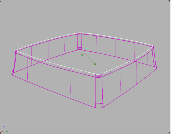
Below is the wireframe to show the resulting surface structure.
Next, we added a new vertical constraint, and this new constraint touches the modifier.
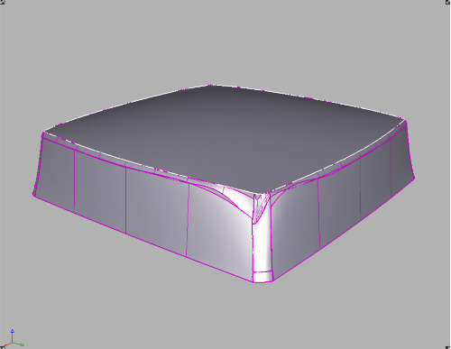
If we now drag the modifier upwards, it causes a conflict at the point where the constraint and the modifier touch, and will result in a warp of poor quality, shown below.
Clampers cannot be used without defining constraints first.
About the Lattice Rig
The Lattice Rig tool uses a lattice to affect global shape modification. The geometry is shaped by moving the lattice points, which squeeze and pull the model. The Lattice Rig tool is especially suited to general volumetric shape changes to a model. Consider using the Lattice Rig for more conceptual and fast explorations.
About the lattice
The lattice is a manipulator in the Lattice Rig tool. It is initialized as a bounding box around the target geometry.
The lattice has two modes: disengaged and engaged. A disengaged lattice is drawn with dashed lines, and when modified, has no influence on the target geometry. This gives you the ability to refine the lattice to suit the intended modifications of the target geometry.
An engaged lattice is drawn with solid lines, and when manipulated, modifies the target’s geometry.
Constraining the lattice
You can shape the disengaged lattice so that it does not fully enclose the targets.
When the lattice is engaged, everything that is outside the lattice remains unchanged; everything that is inside the lattice is modified.
To facilitate this, parts of the lattice that intersect the targets are locked and drawn in red.
In disengaged mode, the lattice points are modifiable; in engaged mode these points are not modifiable.
About dynamic shape modeling
Alias has two tools for dynamic shape modeling: a Lattice Rig tool and a Transformer Rig tool.
Providing two separate tools gives you the following benefits:
- The Lattice Rig is an easy-to-use tool that doesn't require deep user experience.
- The advanced Transformer Rig allows a more detailed and specific shaping process.
Why we developed dynamic shape modeling
The Dynamic Shape Modeling tool family was developed to support global modification of datasets. While it is relatively straightforward to modify just one piece of geometry, it can be a very time-consuming task to change the proportions of an entire model composed of many pieces of geometry. As a designer, you need to explore the proportions of the model. To play with it, you need to be able to modify the whole set of geometry, sometimes as a single unit. The result doesn't need to be a production model, just a model that holds together, expresses the intent of your design, and enables you to make a choice before you finalize your design.
The purpose of dynamic shape modeling
The Dynamic Shape Modeling tools give you the ability to globally change the model easily. Think of it as an advanced non-proportional modification tool that stretches and compresses the model. The basic relationships of parts of your model to each other will not change, and features can not be added or subtracted, but within the model, relative sizes, proportions, and shapes can be modified.
What dynamic shape modeling doesn't do
There is no guarantee that surface continuities are maintained while the global shape is being modified. After the shape modification, check the model, and perform additional work to fix the continuity breaks, as necessary.
What to expect from the tools
Using dynamic shape modeling for communication and concept development
Use these tools for balancing proportions of geometry sets. The output of the tool may not necessarily provide production surfaces, even when the input is of production quality. This tool can easily be used as a communication tool for designers and surface modelers.
Using dynamic shape modeling for further modeling and modification
Because the warping of the global shape does not destroy the surface parameterization, the modified surface set can be used for further modeling. This tool can be used for Class A surfacing work, as long as you realize that further work may be required to bring the model back to production quality.
Common concepts of dynamic shape modeling
While the tool sets have significant differences, they share the following concepts.
Targets
A target is any geometry that is being modified. Targets can be surfaces, meshes, or curves.
Modifiers
A modifier is geometry used to define the desired changes to the targets.
Constraints
Constraints are used to secure parts of the target geometry to prevent shape modifications.
What happens with the target geometry?
As soon as the targets are picked and accepted, the tools duplicate the targets. Shape modifications happen on the duplicated model. The original geometry is made invisible.
While you are modifying the shape of the geometry, the dynamic shape modeling tools allow you to toggle the visibility of the originals and the modified geometry. This makes it easier to compare your modifications with the original.
If, for any reason, the duplicated geometry (visible geometry with dynamic shape history) is modified in such a way that the construction history has to be deleted, the original geometry is set visible and made into a template.
The tools allow you to revert a modification by deleting the duplicated geometry and restoring the original, or commit to a modification by deleting the original and the history.