 Extrude
Creates new subdivision geometry from selected subdivision edges and faces or from curves and NURBS surface edges. Use the Extrude tool to begin forming shapes from primitives, curves or NURBS surface edges.
For example, you can build out you model one segment at a time.
You can extrude from any type of curve, including free curves, curves-on-surfaces, or trimmed surface edges.
Access the tool from the Subdivision Palette:

Subdivision Extrude settings
Direction Type
Specifies the direction of the extrusion.
Normal - Extrudes along the edge and surface U and V directions. The Normal direction is at 90 degrees to the curve or surface direction. Global - Extrude along the X, Z, or Y axes.
Weld Together
When on, continuous edges or faces are merged and extruded.
Edge as New Bodies
When on, a new subdivision object is created from an extruded edge.
Pick Type options
Subdiv Faces - Extrudes only selected subdivision faces.
SubdivEdges - Extrudes only selected subdivision edges and curves.
Curves/Surface Edges - Extrudes only selected curves of all types, including or NURBS surface edges.
All - Performs extrusion depending on the current selection.
Rebuild Curve Options
Divisions
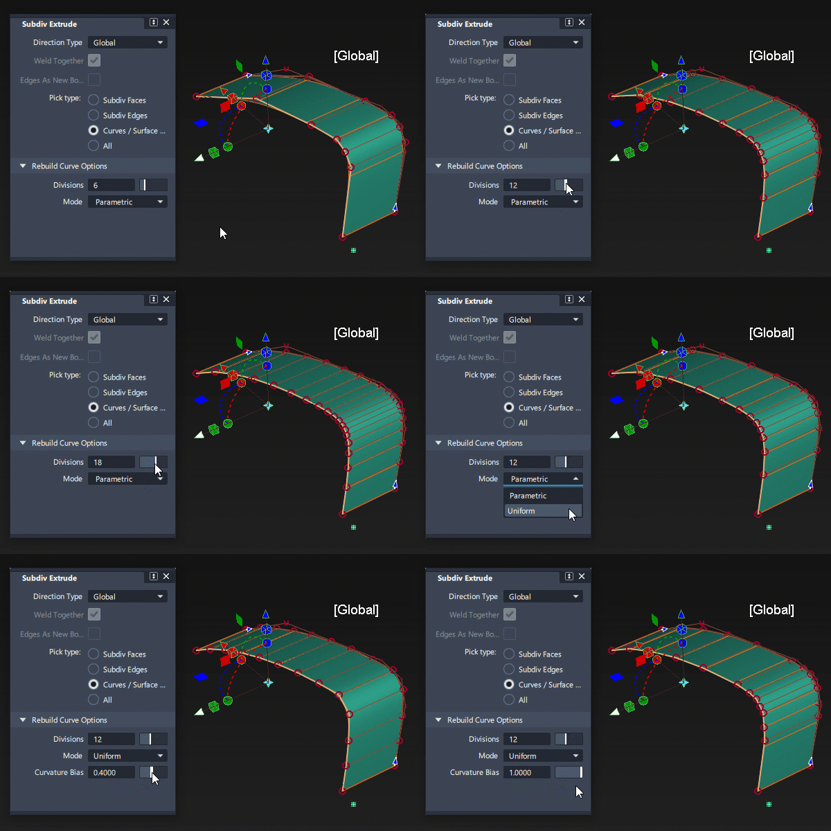
Specifies the number of CVs to add along an extruded curve or surface edge. To use this option, curves and surface edges must be degree 2 or greater.

Divisions: 3 to 10
Mode
Specifies how the CVs get distributed along the extruded curve.
Parametric - Uses the parametric space to distribute the CVs.
Uniform - Distributes the CVs evenly along the length of the input curve. When you select this mode, you can use Curvature Bias to adjust the how curvature affects the distribution. For example, you can add Curvature Bias to distribute more of the CVs to areas with greater curvature.
Curvature Bias
(Available only for Uniform Mode) When set to 0, the CVs are evenly distributed. As you increase this value, the input curve's curvature has a greater effect on how the CVs get distributed. For example, more CVs get placed in the areas of greatest curvature. Use this to produce smoother extruded surfaces particularly around areas with pronounced curvature.
Extrude workflows
Extrude subdivision edge or face
Shift-select the tool to open the control window.
Under Pick Type specify the geometry type to extrude from.
If you select All, the pick chooser appears in the viewport when you select the geometry you want to extrude.
Determine the direction you want to extrude. Select Normal to extrude along the U and V or Global to extrude along the X, Y, or Z axis.
The extrude in-canvas manipulator provides way to quickly toggle between Normal and Global.
Select the geometry entities you want to extrude.
Tip: You can preselect the geometry including edges loops and faces using the Pick tools. Use Shift + MMB to chain-select edges and faces.Use the manipulator to move, scale, or rotate the geometry as you extrude it.
To complete the extrusion, click Extrude Again or press the Spacebar.
Your next extrusion will now builds off the new segment of geometry you've created.
Working with the Rebuild Curve Options
When you extrude from curves or surface edges that are degree 2 or higher, use the Rebuild Curve Options to such as increasing spans and optimizing the CV distribution based on the curvature.
Set the Rebuild Curve Options This includes setting the number of CVs to add along the extruded curve (Divisions), setting how the spans get distributed (Mode), and adjusting how the source curve or edge curvature affects the CV spacing (Curvature Bias).

You make these adjustments before completing the extrusion by selecting Extrude Again.
- Use the Divisions slider to set the number of new spans you want for the new geometry.
- You can set how the new spans get distributed along the length of the curve:
- Select Parameterization to distribute the spans based on parametric space.
- Select Uniform to distribute the spans evenly alone the curve. When you use this option, an additional setting, Curvature Bias is available. This lets you optimize the placement of the spans to maintain the original shape of the source curvature. Increasing this value distributes more spans in the areas of highest curvature. This generates smoother curves in the subdiv model.