Revolve
The standard revolve function is Freeform which creates a surface of revolution by sweeping curves around an axis. The secondary function of revolve is to create an automotive side glass surface using a Barrel or a Helix construction.

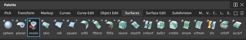
Access this tool from the Surfaces palette:
Revolve settings
Axis Options

There are four ways to define the axis of revolution:
- Local + X, Y or Z. Axis position is defined by the pivot point of the curve or group. Axis direction defined by an X, Y or Z direction. Only one curve or group of curves can be selected when using Local mode.
- Global + X, Y or Z. Axis position is defined by scene origin. Axis direction defined by an X, Y or Z direction.
 The setting in the control window will change accordingly and you can continuue with the workflow for Revolve.
 Surface Type : Freeform, Non-Periodic
Sweep Angle - The total angle of revolution (in the current angular units). After creating the surface, you can also change this angle by using the manipulator handles.
Per Segment - Specify the sweep angle per segment. This will be automatically set when the Segments value is changed to create an equal division. If this is then subsequently modified, and the sweep angle per segment does not divide equally into the total sweep angle then the last surface will be a smaller surface containing the remainder.
Segments - Specify the number of individual surfaces that will form the revolution. The surfaces each have the same sweep angle, are grouped, and curvature continuous with each other.
Degree - The degree in the V direction of the new surface, from 1 to 7, with 5 being the default.
Spans - The number of spans in each segment of the revolved surface. When building non-periodic revolves, this is typically set to 1 to create single-span (Bezier) surface segments.
Pitch - Specifies the displacement of the curves (along the axis) over one complete revolution.

Selecting Freeform, but not Periodic creates an 'open' revolved shape if only one span is selected, or a group of adjoining surfaces if more than one span is selected.
Surface Type : Freeform, Periodic
Degree - The degree in the V direction of the new surface, from 1 to 7, with 5 being the default.
Spans - The number of spans in the revolved surface. For a periodic surface this will affect the 'circular' accuracy. The default is 12 spans and this will give reasonable accuracy for concept design.

Selecting Freeform and Periodic creates a 'closed' 360 degrees surface.

Revolve Side Glass settings
Surface Type : Side Glass - Barrel
Barrel – Creates a section of a surface of revolution through the specification of five points: 3 that define an arc of revolution and a further two that define an intersecting arc (the barrel curve).
Helix – Creates a section of a surface of revolution through the specification of one or more curves, and two points that define an intersecting arc of revolution.
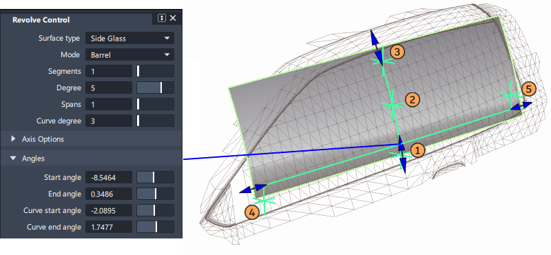
To build a barrel sideglass five points are specified (typically snapped onto a reference surface or mesh) plus an axis direction - (typically the x-axis for a vehicle with the centre-line along X):
- The first three points describe the 'vertical' arc.
- The fourth and fifth point are added to the first to describe the lengthways arc.
The selected points can be adjusted by click-drag after the surface is created, and the extents of the surface adjusted with the blue arrows.
Segments, Degree and Spans settings are as described above.
Curve degree - Specifies the degree of the barrel curve (the second arc), which becomes the degree of the barrel surface in the U direction.
Start angle/End angle - Specify the angle between the start/end points of the arc of revolution and the barrel or helix curve. These values are also controlled by arrow manipulators on the model.
Curve start angle/Curve end angle - Specify the angle between the start/end points of the barrel curve and the arc of revolution. These values modify the extent of the curve. They are also controlled by arrow manipulators on the model.
![]()
Surface Type : Side Glass - Helix

This is similar to the barrel side glass surface, except that a curve is used for the length-way arc:
To build a helix sideglass:
- Select the arc curve and hit the Accept button.
 Specify two additional points to describe the 'vertical' arc.
- In the Revolve Control Window, choose the axis direction - typically the x-axis for a vehicle with the centre-line along X.
- Optionally apply a Pitch value to twist the surface.
Segments, Degree and Spans settings are as described above.
Pitch - Specifies the displacement of the curves (along the axis) over one complete revolution.
Start angle/End angle - Specify the angle between the start/end points of the arc of revolution and the barrel or helix curve. These values are also controlled by arrow manipulators on the model.
Revolve common parameters
Revolve has the following Surface Tool Common Parameters sections:
- Axis Options
- Control Options
Revolve workflows
Creating a revolved surface
The Revolve tool is best used with the Control Window open, so that values can be modified interactively.
Be aware of the Rational settings that are selected in the Construction Options, as these will affect the CV structure of the revolve surface.
Select the Surfaces > revolve tool and follow the prompt line
Creating a revolved surface using a Vector
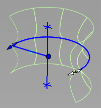
To use a vector to define the axis of revolution, you can either create a Vector first, or use the manipulator:
Picked. First create a vector (which defines the direction and location of the revolve axis), and then select this before or after selecting the curve(s). It is not necessary to select the Picked option in the Control Window, as this will be automatically set when a vector is selected.
Manip. When the manipilator is modified this option becomes selected to indicate that the Control Window values are being changed in the modeling view.
To use the manipulator:
- Click a handle, then drag the mouse left or right to change the value.
- Click any of the handles and type exact values.
There are three buttons used to manage and create vectors:
Refresh Vector - This button only appears if View is selected. Click it to update the vector if the view has been modified.
Retain Vector - Converts the selected X,Y,Z or View direction to an independent vector in the scene. The tool window changes to 'Picked', and the projection direction is now controlled by the vector created.
Create Vector - This option allows you to create a vector by selecting two points, or select an existing vector, followed by the 'Accept' button. This is then used as the axis for the revolve.
Creating a spring or helix surface
- Create a curve to define the cross-section of the helix.
- Position the curve at a distance from the required centre-line of the helix, and oriented in the plane of that axis.
- Shift-select the Revolve tool.
- Select the axis direction (e.g. X,Y or Z) - if using Local axes make sure the pivot point of your curve is positioned at the axis position required.
- Modify the pitch value to create an offset for the revolve.
- Modify the Sweep Angle value to define the number of rotations (note that this value can only be increased above 360 degrees if a pitch value has been added).
- Modify the Spans or the Segments to create sufficient CVs in the surface(s) to conform to the helix shape.
Creating a Side Glass surface
A side glass surface is usually constructed on top of scan data, or a concept surface, and so the input points can be snapped to reference.

About rational and non-rational geometry
Non-rational geometry is a sum of polynomials. Rational geometry is a ratio of sums of polynomials. Rational geometry is considerably more complex mathematically. Therefore:
- It may not be transferable to downstream CAD packages that can’t deal with complex descriptions
- It can be slower to manipulate when modeling, and slower to render.
The following tables lists the differences between the two types of geometry.
| Nature | Pros | Cons |
|---|---|---|
| Non-rational | More flexibility for transformations.Faster. | Sacrifices some precision for modeling flexibility. |
| Rational | Precise geometry (that is, exact conics). | Weighted CVs not supported by many CAD packages. Weighted CVs harder to manipulate.Creates multi-knots.Slower to display and render. |
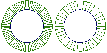
This illustration shows two circles drawn with the two types of geometry.
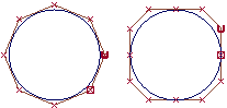
- The circle on the left is a non-rational curve with CVs that are all weighted equally. To have a non-rational curve, all weights must be 1.0.
- The circle on the right is a rational curve with different weights applied to the CVs, and multi-knots.
You can see the difference in two ways:
If you attach a radius measurement to the circles, the non-rational circle is not a perfect circle (although it is close): it has different radii depending on where you measure. The rational circle is a perfect circle.
Attach curve curvature combs to the circles. The curvature on the non-rational circle on the left varies. The curvature of the rational circle on the right is constant.