Surface Fillet
Builds a fillet surface between two sets of surfaces. These can be automatically trimmed to create a continuous flow of surfaces.
It is typically used to build balanced blends between the primary surfaces of a design.
Small detail fillets can also be built, but the Round tool should also be considered as it will calculate a corner blend where three or more edges come to one point.
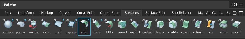
Access this tool from the Surfaces tool palette:
Related video
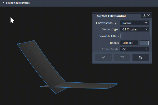
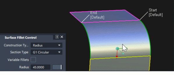
Surface Fillet settings
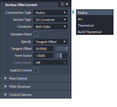
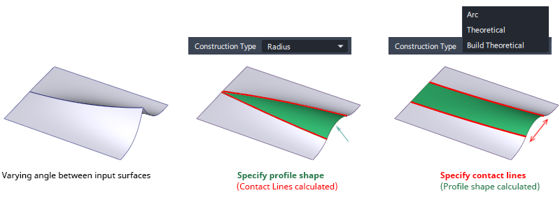
Construction Type

Radius
With Construction Type set to Radius - you specify the profile shape by a Radius value (or a Center radius / Tangent length value for non-circular fillets). The contact lines are then calculated by the surface fillet tool.
For the following three options you specify the position of the contact lines . The profile shape is then calculated by the surface fillet tool.
- Arc (Chord) – Creates a symmetrical arc type of fillet. The fillet 'theoretical' may differ from the true theoretical intersection of the input surface sets.
- Existing Theoretical - Uses the true theoretical intersection of the input surfaces to build the fillet. Creates the most technically accurate width-specified fillet.
- Build Theoretical - Generates a theoretical intersection using an offset method.
Section Type
These options control the profile shape of the fillet by imposing different continuity levels with the input surfaces on each contact line:
- G0 Chamfer – Creates a chamfer edge between the two sets of surfaces with position continuity with the surfaces on either side. The Crown option only becomes available when chamfer is selected.
- G1 Circular – Creates a fillet with circular cross-section, tangent to both sets of surfaces. This type maintains tangent continuity with the surfaces on either side.
- G2 Curvature – Maintains curvature continuity (G2) with both sets of surfaces. G2 continuity means that the curvature (which is the inverse of the radius of curvature) is the same on both sides across the fillet’s boundaries.
- G3 Curvature – Maintains G3 continuity with both sets of surfaces. G3 continuity means that the curvature’s rate of change is the same on both sides across the fillet’s boundaries.
- G2 Curvature/Arc – Creates a fillet that has a short lead-in with curvature. This type maintains a true arc-shaped section between the two sets of surfaces. Use the Bezier option to create three surfaces instead of a multi-span surface.
When calculating the fillet, the V degree is adjusted so that the surface has enough CVs to provide the required continuity on both sides. Degree 5 is needed for G2 Curvature and degree 7 is needed for G3 Curvature.
Curvature
(Appears for G2 & G3 Section Type only)
- Both - (Default) Make the fillet surface curvature continuous with both sets of surfaces.
- Side 1 - Make the fillet surface curvature continuous with the first set of surfaces (Pink) and tangent to the second.
- Side 2 - Make the fillet surface curvature continuous with the second set of surfaces (Yellow) and tangent to the first.
Variable Fillets
If this option is checked, you can set the radius or chordal length/tangent length at different points along the length of the fillet (see section below).
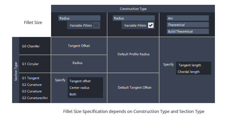
Fillet Size and Specify
To change the size of a fillet surface, we would typically think of the size as a radius value. And for a simple G1 Circular fillet that is the option that is shown.
However, depending upon your selection of Construction Type and Section Type, one of four size options may be shown:
These are illustrated below with circular fillet and chamfer fillet examples:
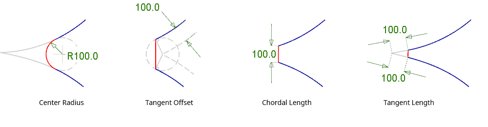

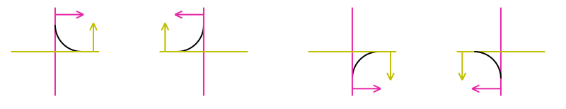
- Radius or Center radius - This is the standard 'rolling ball fillet' definition where the user specifies a radius value and the Fillet tool calculates the contact lines.
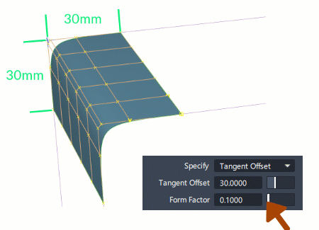
- Tangent offset - The contact lines for the fillet are calculated by offsetting the input surfaces, and then striking a line from the intersection of the offsets perpendicular to the original surfaces. The distance of the offset is called the Tangent Offset. This can be thought of as the same contact lines as would have been produced by a circular fillet of the same radius value.
- Chord length - The distance between the contact lines. The user specifies a fixed width, and the Fillet tool calculates the radius.
- Tangent length - The straight-line distance along the surface tangent direction, outward from the contact lines. The user specifies a fixed length, and the Fillet tool calculates the radius.
The size parameter displayed for different combinations of Construction Type and Section Type is shown in the table below:
Form Factor
The Form Factor controls the shape of a fillet or blend when G1 Tangent or G2/G3 Curvature are selected.
The value is between 0.1 ('sharper') and 2 ('flatter'), with a value of 1 being equal spacing.

The Form factor determines the ratio between the lengths of the boundary hull and the central hull(s). Hulls between the boundary and central hulls are interpolated linearly.
Surface Fillet advanced settings
G2 Curvature/Arc settings
Auto Adjust Sliders
Automatically sets the Form Factor and Arc Range values to produce the optimal shape as you adjust the Lead-In value. This lets you quickly arrive at the optimal fillet shape and curvature comb without constant adjustment of these three settings.
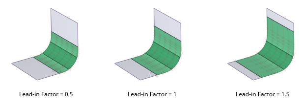
Lead-In
Sets the length of the fillet lead-in. For best results, turn on Auto Adjust Sliders while adjusting this value.
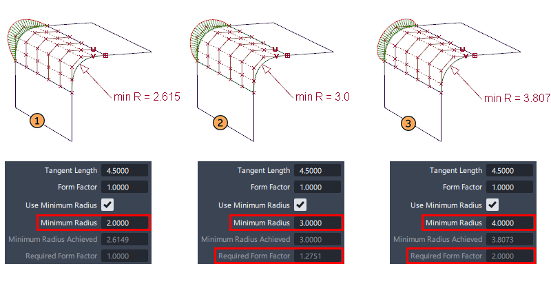
Use minimum radius
This option appears when the fillet width is specified using Construction Type: Arc (Chord), Existing Theoretical or Build Theoretical. With these Construction Types, you cannot explicitly set a radius value.
The Use minimum Radius option checks that no part of the fillet surface falls below a set value, and if it does, adjusts the Required Form Factor to modify the fillet profile to ensure the Minimum Radius value is not violated. This is typically needed for safety or legislative requirements.
There are three potential outcomes, with the read-only fields giving information on the results:
- If the fillet does not create any part of its surface with a radius less than the Minimum Radius value, then the result is the same as if Use Minimum radius had not been selected.
- If modification is required, the two read-only fields provide information on how the Form Factor has been modified to achieve the required minimum radius.
- If a Required Form Factor greater than 2 would be needed to achieve the required minimum radius, then it won't be achieved and the the actual minimum radius is displayed. In this case you would need to increase the chordal or tangent Length value of the surface fillet to achieve the desired minimum radius.
Surface Fillet flow control
Surface Fillet has two unique Flow Control options: Auto and User defined in addition to the standard settings given in the Surface Tool Common Parameters sections.
Auto
The Auto option is the default, and it automatically chooses the best option for each setting based on the input geometry. The options can still be changed using the in-canvas locators or the Control window settings.
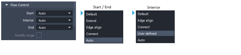
User Defined
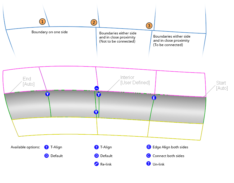
The Interior setting for Flow Control has an additional User Defined option that appears when there are interior boundaries in the input surface sets.
When selected, icons appear at each boundary which can be used to individually modify the settings for each one. (All other settings for Interior will affect all boundaries with one setting.)
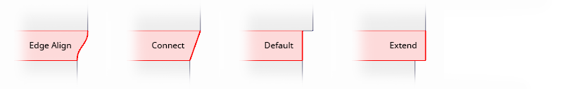
Clicking on the icon cycles through the settings that are applicable to each boundary situation:
 - Edge Align to both sides.
 - Connect
 - T-Align - Align to one side only. Also used to un-link boundaries.
 - Default
 - Use to re-link input surface boundaries to create a single fillet surface boundary.
There are three different scenarios that allow for different groups of settings to be selected:
- T-Junction (with no nearby boundaries on the other side)
- Two T-junctions on opposite sides, close to each other.
- Two T-junctions on opposite sides, close to each other, linked to form a single boundary in the fillet group.
Variable Fillets
Choosing Variable Fillets in the control window displays the 'fillet guide curve' in blue (in effect the theoretical intersection of the input surface sets).
This has a parameter range from 0 to 1 and any number of size locators can be positioned along it, and the fillet surface will blend between the different size values.
To create a variable radius fillet:
- Select the Variable Fillets check box to on.
- Click on the blue line to add an additional radius manipulator.
- LMB Click and drag on a manipulator to change the radius value interactively.
- MMB Click and drag on a manipulator to change the location along the line interactively.
- Keyboard Entry - size - click on the manipulator arc so that it is displayed in white, type the size value followed by Enter.
- Keyboard Entry - position - click on the manipulator straight lines so that they are displayed in white, type the position value (0-1) followed by Enter.
Surface Fillet common parameters
Surface Fillet has the following Surface Tool Common Parameters sections:
- Continuity
- Form Factor and Fillet Specify
- Explicit Control
- Flow Control and Modify Range
- Surface Structure
- Control Option
Surface Fillet workflows
Selecting Inputs for Surface Fillet
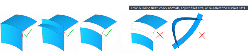
The fillet surface will be built between two surfaces, or two surface sets which are G1 Tangent continuous. These can be chosen with a box-select or with individual clicks.
Input Set 1 will be displayed with pink boundaries. Input Set 2 will be displayed with yellow boundaries. It doesn't matter which set is pink or yellow - they are treated exactly the same.

Surfaces can be added or removed before clicking the Build button, or the Update button. Additional surfaces will be added to whichever input set they are G1 Tangent continuous with. (The Selection Options settings for mouse button behaviour are respected - default is RMB to remove, LMB/MMB to add).
Choosing Fillet Quadrant
Pink and Yellow arrows are displayed to choose the resulting position of the fillet. In most cases, the tool will direct the arrows on the correct side, but if you need to change them, click on either arrow to change the direction before using the Build button.
Note that using Query Edit doesn't re-invoke the arrows, and so the directions cannot be changed after the fillet has been built. In this case, undo the fillet and build again, correcting the arrow directions before using the Build button.
Proximity
The two Input Sets need to relate to each other in a way that allows the fillet surface to build:
Tips:
- Use the Extend tool on the input surfaces if the gap is too large. (In production-quality surface modeling it is typically good practice to extend the surfaces to a 'theoretical intersection'.)
- If you have surfaces that intersect twice, make copies and use Detach or Trim to split them. Create the fillets to these surfaces and then template or discard them. Trim the original surfaces to the fillet edges.
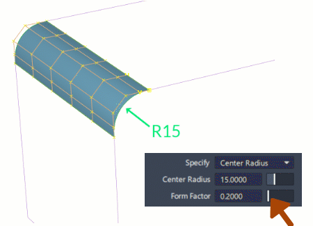
Specify Fillet Size with Form Factor
When using a Section Type of G1 Tangent, G2 or G3 curvature, a Form Fillet value is added, and you have a choice of how to specify the Fillet Size.
Specify the Centre Radius value when you want to maintain a constant peak radius, while adjusting the length of the lead-in using the Form Factor. The contact lines will change as the Form Factor is modified.
Specify the Tangent Offset, Chordal Length or Tangent Length when you want to maintain constant contact lines for the fillet, while adjusting the shape using the Form Factor. The peak radius will change as the Form Factor is modified.
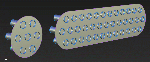
Creating Fillet Surfaces using Multiple Input Surfaces
Many fillets of the same size can be created in a construction history 'group'. These can then all be modified by a single Query Edit operation, with a single value.
This is the only situation where the order of selection is important (also the selection behaviour of each mouse button):
- Select one or all of the 'slab' surface(s) first - this will be Input Set 1 and displayed with a pink boundary.
- Select one of the 'pattern' surfaces - this will be Input Set 2, displayed in yellow and is where the direction arrow will be shown.
- Select all of the remaining surfaces. This will be Input Set 3 and is displayed with white boundaries.
Alternatively...
- Box pick all the surfaces in one go - making sure the initial position of the box-select is on one of the slab surfaces.