 Fillet Flange
Fillet Flange maintains the selected boundary of the input surfaces as the specification for the finished component. A rolled-edge fillet surface is then built to match this boundary, and optionally a flange added.
The input can be an edge, curve-on-surface, boundary edge, or iso-parametric line.
With Fillet-Flange, the fillet surface is created first to maintain the original perimeter to within manufacturing requirements. A flange is then added if required (image 1 below).
This gives control over the edge which is often preferable to building a flange first and constructing a fillet second, as this will always eat away from the original edge perimeter (image 2 below).

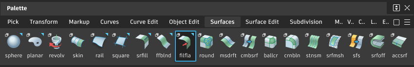
Access this tool from the Surfaces palette:
Fillet Flange settings
Wall

Type (Wall)
Set to either Draft or Normal.
In Draft mode, the Draft Vector Options section will appear and a direction can be selected.
Normal builds at 90 degrees to the surface.
The wall is used to ensure that the rolled-edge component has the same perimeter as the original design surface in your chosen view direction.
The wall is a temporary construction surface which is not built as a true surface. A proxy of the wall can be displayed using the Show Wall setting in the Control Options at the bottom of the tool window.
Angle/Draft Angle
Modify the direction selected above by adding an incremental angle.
Flip (Wall)
Swaps the direction of the temporary wall, so that the fillet will be built on one side or the other. You can also click the blue arrow manipulator on the model to flip the side.
Fillet

The rolled part of the built surface is created as a fillet using the standard settings described in Surface Fillet
Flip (Fillet)
Enables you to flip the fillet on the other side of the wall. This option is grayed out if at least one of the input curves is an edge, and thus, it’s possible to build a fillet only on one side of the wall.
Flange
These settings determine the revolved extent of the fillet surface (shown in red). The position and tangent direction of the end of the fillet is used to define the added flange surface (shown in green).

Type (Flange)
Set to either Sweep Angle or Parting Line.
Sweep Angle - Define the revolution angle of the fillet surface. If a flange is created, this will define the start point and direction, tangent to the fillet end.
Parting Line - The fillet is rotated until its end tangent is in the specified parting line direction. Use the Parting Line Vector Options section to set the pull-direction.
Sweep Angle / Draft Angle
Provides a slider to control the angle. The default is 90 degrees for Sweep, and 0 for Draft angle. Either angle can be variable.
Create Flange
Determines whether or not a flange will be built off the edge of the fillet. Note that the fillet will be trimmed according to the Sweep Angle or Parting Line settings, even if Create Flange is off.
Length
Determines the length of the flange that will be built, if Create Flange is on. Length can be variable.
Control Options
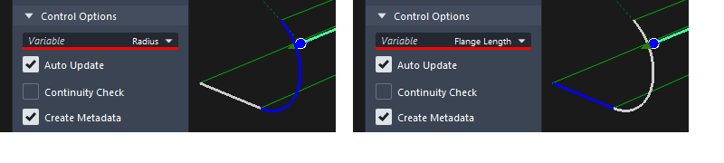
Variable
Gives you the ability to interactively modify the Flange Length, Flange Angle, or Radius. Only one of the three parameters can be variable. For example, it is not possible to create a variable radius fillet with a variable length flange.
Use the In-Scene Manipulators to set-up the variable values along the input edge.
Show Wall
Displays the imaginary wall that is used in the calculation of the fillet.
Fillet Flange advanced settings
Shift Method
The Shift Method controls which parts of the geometry stay within the wall geometry.
If your chosen flange settings create a tucked under fillet-flange then the Shift method settings wont change the result.
If the flange sticks out then the the fillet-flange surfaces may be shifted along the input surface if this is required to satisfy engineering requirements. See below:

Off - No constraints are applied to the built surfaces. The underlying fillet shape always stays within the wall, but if the sweep of the fillet is small the actual fillet surface may sit behind the input edge.
Fillet Only - (Default) The fillet surface will be adjusted to fit within the wall envelope.
Flange + Fillet - Both the fillet and the flange surfaces will be adjusted to fit within the wall envelope.
Fillet Flange common parameters
Fillet Flange has the following Surface Tool Common Parameters sections:
- Continuity
- Form Factor and Fillet Specify
- Explicit Control
- Axis & Vector Options
- Flow Control and Modify Range
- Surface Structure
- Control Option
Viewport manipulators
The following manipulators appear when you create new fillet-flange surfaces, or when you use Object Edit > Query Edit to re-engage the history.
Radius/Length/Angle - Only one of the parameters can be varied, the other two are held constant. The variable parameter is drawn in blue on the manipulator and can be changed using the Variable setting in the Control Options.
Flip - Click on an arrow to flip the direction.
Extend - To toggle an extension (to achieve a trim operation) click the green arrow appearing at that end. The arrow is shown in light green when extension is on. If the rail is closed, that is, its endpoints coincide, extension is not useful, and, therefore, the arrows are not shown.

Working with the manipulator
The arc and line shows the Fillet value (radius) and the Flange settings (angle and length). Only one of these can be modified, and the variable one is displayed in blue:
Click and drag on the blue section of the manipulator to interactively change the value.
Click-release to highlight in white, and then type a value in the prompt line.
he ball can be used to drag the manipulator along the input line, or selected and a value (0-1) entered in the prompt line. This is only useful if more than one manipulator has been applied (see below).
Adding manipulators for variable radius, length or angle
To add a new manipulator, Shift - left click on the desired point on the rail. Click and drag on the ball to move the manipulator position interactively, or click-release to highlight in white and use the prompt line to enter a value between 0 and 1.
To delete a manipulator, Shift - right click on it.
As soon as another manipulator is added, the value in the control box is grayed out, as it is now possible to modify each manipulator independently to create a variable fillet-flange.
