 Tube Flange
The Tube flange tool provides a solution for an edge finish where the focus is on the contact line and when it is important, for aesthetic reasons, to control the line where a highlight is changing.
By using one or more of the following: edge, curve-on-surface, boundary edge, or iso-parametric line, the tool creates a tube that touches the selected geometry. The tool also creates a linear extension — a flange — on the tube. This extension can be defined by a sweep angle or a draft vector direction.
Access this tool from the Surfaces palette:
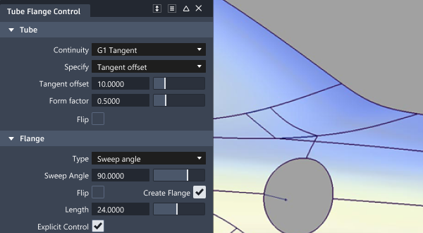
Tube Flange settings
Tube (Fillet)

The tube part of the built surface is created as a fillet using the standard settings described in Surface Fillet
Flip (Fillet)
Enables you to put the tube and flange on top of, or underneath the surfaces. You can also click the blue arrow manipulator on the model to flip the side.
Flange

Type
Set to either Sweep angle or Parting line.
Sweep angle defines where along the tube the flange will be tangent to the tube. Parting line uses a vector and draft angle that determines the direction of the flange.
If you select Parting line, you must pick a vector, or specify it through the Parting Line Vector Options.

Sweep Angle / Draft Angle
Provides a slider to control the angle. The default is 90 degrees for Sweep, and 0 for Draft angle. Either angle can be variable.
Flip
Enables you to flip the direction of the flange. This option is grayed out if at least one of the input curves is an edge, and thus, there’s only one valid orientation of the flange.
Create Flange
Determines whether or not a flange will be built off the edge of the tube. To create a full tube, use a Sweep Angle of 360 degrees. Note that the tube will be trimmed according to the Sweep Angle or Parting Line settings, even if Create Flange is off.
Length
Determines the length of the flange that will be built, if Create Flange is on. Length can be variable.
Control Options
Variable
Gives you the ability to interactively modify the Flange Length, Flange Angle, or Radius. Only one of the three parameters can be variable. For example, it is not possible to create a variable radius fillet with a variable length flange.
Use the In-Scene Manipulators to set-up the variable values along the input edge.
Tube Flange common parameters
Tube Flange has the following Surface Tool Common Parameters sections:
- Continuity
- Form Factor and Fillet Specify
- Explicit Control
- Axis & Vector Options
- Flow Control and Modify Range
- Surface Structure
- Control Option
Viewport manipulators
The following manipulators appear when you create new tube-flange surfaces, or when you use Object Edit > Query Edit to re-engage the history.
Radius/Length/Angle - Only one of the parameters can be varied, the other two are held constant. Choose which using the Variable setting in the control window.
Flip - Click on an arrow to flip the direction.

The 'arc and line' shows the Fillet value (radius) and the Flange settings (angle and length). Only one of these can be modified, and the variable one is displayed in blue.
Click and drag on the blue section of the manipulator to interactively change the value.
Click-release to highlight in white, and then type a value in the prompt line.
he 'ball' can be used to drag the manipulator along the input line, or selected and a value (0-1) entered in the prompt line. This is only useful if more than one manipulator has been applied (see below).
Adding manipulators for variable radius, length or angle
To add a new manipulator, Shift-left click on the desired point on the rail. Click and drag on the ball to move the manipulator position interactively, or click-release to highlight in white and use the prompt line to enter a value between 0 and 1.
To delete a manipulator, Shift - right click on it.
As soon as another manipulator is added, the value in the control box is grayed out, as it is now possible to modify each manipulator independently to create a variable fillet-flange.
Tube Flange workflows
Pick edge curves for the Tube flange and Fillet flange tools
Select one part of the edge to be selected.
Click-drag a pick box over the rest of the edges to be selected.

The curves forming the edge are selected.

After the edge is selected, you can select vectors to define the flange when the parting line method is used.
Create a tube
The Tube flange tool creates a tube touching the selected geometry (curves-on-surface, iso-parametric lines, or surface edges).

The tube has parameters that can be modified in the option window.

If you create a tube with G1 Tangent continuity, the tube is created with 360 degree sections. It will be trimmed to an appropriate section when creating the flange.

If you create a tube with G2 Curvature continuity, the tube will lose the 360 degree section, and be created between the contact line and the flange.

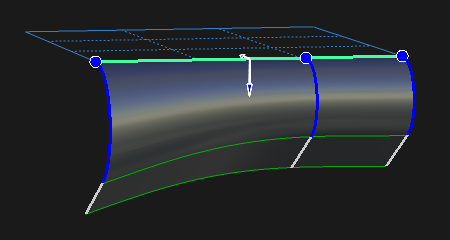
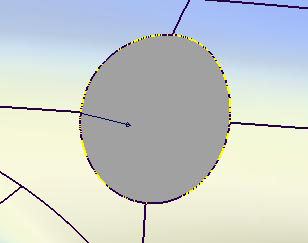
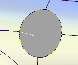
The image below shows a model with a tube and flange on both sides of the surface. Using the Flip checkbox in the control window (or blue arrow manipulator), you can specify on which side the tube will be built. A similar checkbox is available to control the direction of the flange if the tube is constructed on an interior isoparametric curve or a curve-on-surface. For tubes built on edges, the orientation of the flange is unique, and cannot be flipped.

Create a flange
There are two methods to calculate the flange at the end of the tube section. They are:
Sweep Angle
Parting Line

Based on a vector (selected by clicking it with the left mouse button, or specified through the option window), the tool analyzes the parting line and creates a linear extension called a flange.
Detailed workflow
Shift-select the Tube Flange tool.
Select the geometry requiring an edge finish. Keep in mind that you can drag a pick box over the surface curves to be selected, or turn on Chain Select under the Control Options to select tangent continuous curves all at once. Clicking the geometry again de-selects it.
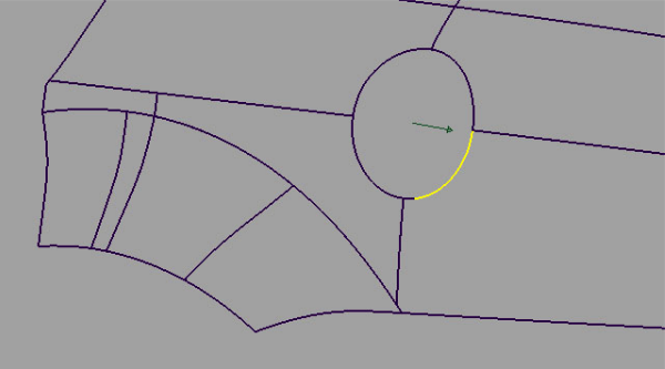
With the Flange type set to Parting line, the vector defining the flange direction must be selected using the left mouse button. When selected, the vector turns white. The vector can also be specified through the Parting Line Vector Options.
Click the Update button in the lower right section of the window.

If the flange is not needed, make sure the Create Flange box is not checked.
The Surface Structure section of the control window provides options to modify the span placement of the generated geometry. Setting Surface Type to Single surface creates a single tube and flange surface, otherwise the tube and flange are split at curve boundaries, which also include surface boundaries, since a curve cannot span more than one surface. This may provide you with better results, in terms of multi-span geometry. See the section Troubleshooting trimmed surfaces for more information.
