 Square
Creates a surface by blending between four boundaries. The boundaries can be free curves or surface edges, isoparms or curves-on-surface.
They must also intersect at the corners to describe a closed shape.
When the boundary is a surface edge or curve, then continuity can be requested to the input surface. This makes square a valuable tool for creating smooth, blended designs. When a boundary is on the centre-line of a symmetrical design, Implied Tangent continuity can be used to ensure a smooth result when the surfaces are mirrored.
Related video:
 Boundary Surfaces.
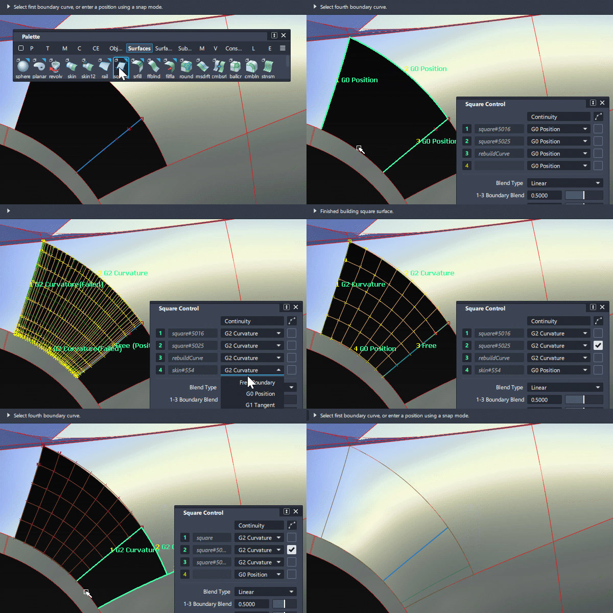
Access the tool from the Surfaces tool palette:

Before using the Square tool
Boundaries
The boundaries selected for the square surface must meet the following criteria:
The boundary curves must touch or intersect at the corners (to withing the G0 position tolerance set in Construction Options). If modifications to the boundary curves cause them to stop intersecting (while construction history is on), the square surface will have a dotted boundary indicating that it cannot build.
Two adjacent input edges must not be colinear. If they are, the square will build but the flow of hulls will not produce a good surface.
Each boundary must be a separate entity. If two boundaries are segments of the same curve or edge, they must be separated by using detach or trim.
Continuity
For continuity to be achieved on a boundary of the square:
The two adjacent boundaries must also have the same level of continuity with that boundary. When this is not the case, the continuity will typically fail and there will be an increase in isoparms in the affected corner.
For the Implied Tangent setting to work on a centre-line boundary, the two adjacent curves or edges must also have implied tangency.
If a boundary surface has been built using a curve, and the curve is visible, make sure that you select the surface not the curve when choosing inputs for the square. Only G0 continuity can be calculated to a curve.
Square settings
Continuity table and rebuild

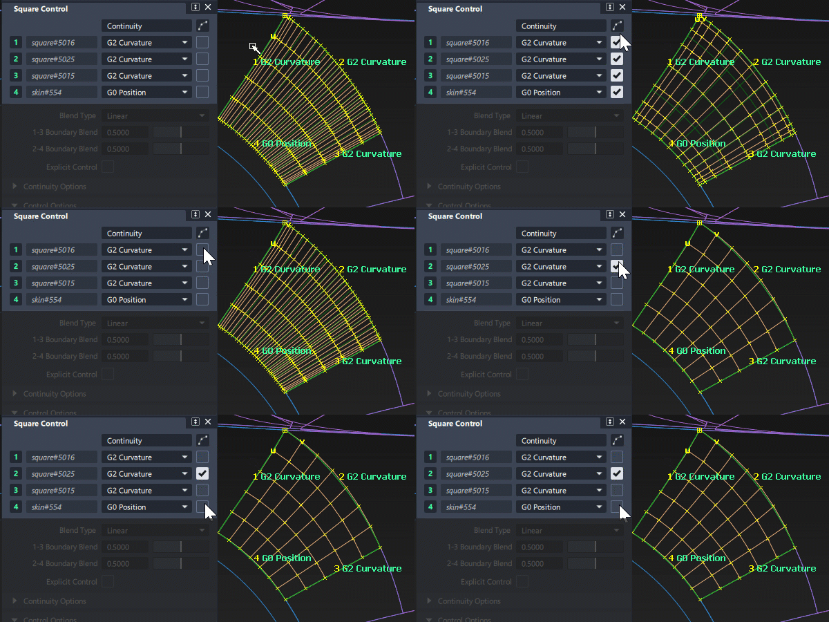
The Continuity table displays one row for each boundary. Use this to select the continuity and rebuild settings:
 Use the title pop-up menus to adjust the settings for all 4 boundaries.
 Use the pop-up menu and checkbox on each boundary to adjust individually.
Continuity
Select the Continuity you want for each boundary. See Surface Tool Common Parameters for explanations of each continuity option.
Rebuild
The Rebuild option can improve the parameterization of the square surface by attempting to reduce the number of spans while maintaining accuracy to within the Construction Tolerance settings.
Rebuild can help when building from trimmed edges, and when input edges on opposite sides have different degree or spans.
Blend Type
Linear/Cubic
Blending gives you influence over the interior of the square surface. The boundaries are constrained by the input curves and edges.
Use the sliders to nudge the surface towards one boundary shape or the other.
1-3/2-4 Boundary Blend
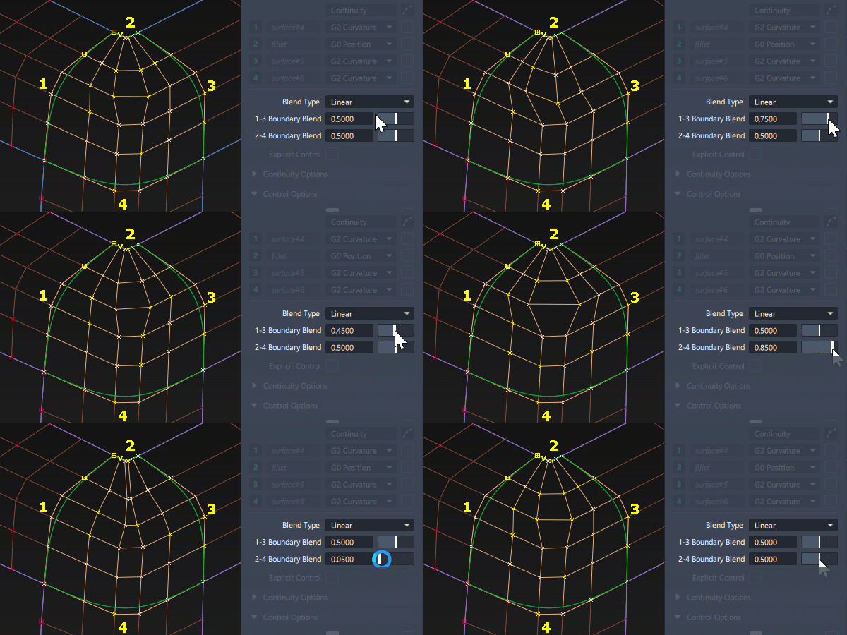
These sliders control the point of equal influence of opposite boundaries (in other words, the midpoint of the blend between opposite boundaries): that is, between 1 and 3, and between 2 and 4. Values can effectively range from 0.17 to 0.83.
Continuity Options
These options only appear if Explicit Control is turned off. In practice Explicit Control is often preferred as a method of influencing the surface structure.

Max. New Spans
Maximum number of spans the Square tool can insert on each edge of the new surface as it tries to achieve continuity. If the Square tool cannot achieve tangency without inserting more than the allowed number of spans, it displays an error in the prompt line.
Insert at Midpoint
When selected, insert extra edit points at the midpoint of the span with the largest continuity deviation. This is the default, and results in a better distribution of the isoparametric curves. When not selected, insert extra edit points at the location of the largest continuity deviation.
Colinear Options
Boundary 1, 2, 3, 4
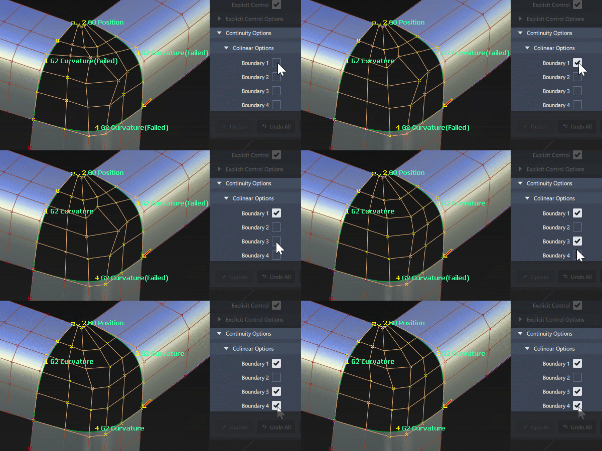
When an input boundary has a flow of Hulls and CVs that you want the new square surface to match, use the colinear option. Only applies when G1 Tangent or G2 Curvature continuity is selected for that edge.
Be careful not to use colinear on edges where the CV flow would distort the square surface being built (some trimmed edges for example).
Also be careful not to leave the settings on when moving onto another square surface. If the co-linear options are selected in the wrong circumstances you can get poor results. A good trouble-shooting tactic is to always check that the colinear settings are off, unless you have specifically set them to be on.
Square advanced settings
Blend Type
Linear – Builds the interior of the surface using only information about the boundary curves. The interpolation of the boundaries is linear. The free CVs of the four boundary curves (CVs not controlled by the continuity options) are blended.
Cubic – Builds the interior using tangent for tangent continuity edges, or tangent and curvature information for curvature edges. The interpolation of the boundaries is cubic when only tangent continuity is needed or quintic when curvature continuity is needed.
Depending on how much the tangent and curvature ribbons change, cubic blends can be much wavier than linear blends.
Example: G1 Tangent continuity along one boundary

Linear blending – Notice that the hull forms approximately a straight line from the third CV row onward.

Cubic blending – The third CV row and onward is rounder and less flat. The Tangent direction (2nd CV row) is being blended into the surface interior.
1-3/2-4 Boundary Blend
These sliders control the point of equal influence of opposite boundaries, in other words, the midpoint of the blend between opposite boundaries): that is, between 1 and 3, and between 2 and 4. Values can effectively range from 0.17 to 0.83.
Changing the surface using the Boundary Blend sliders is slow, because continuity must be recalculated. For very complex surfaces, or when using G2 Curvature or Tangent Angle continuity, you may want to turn off the Auto Update option.
1-3/2-4 Influence
These sliders control how much each set of boundary curves influences the new surface.
They only appear when Blend Type is Cubic.
For example, if you set the 2-4 Influence slider to 0.0, the new surface will mostly blend between edges 1 and 3, and will have little of the shape of edges 2 and 4.
Changing the surface using the Influence sliders is much faster than with the Boundary Blend sliders, because continuity is not affected.
Square common parameters
Square has the following Surface Tool Common Parameters sections:
- Continuity
- Explicit Control
- Control Options
Viewport manipulators and locators
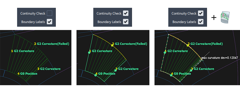
Boundary Labels and Continuity Check
The Boundary Labels are on by default, and they report whether the square surface has achieved continuity to within the Construction Tolerances.
The Continuity Check displays the achieved and failed continuity, using the same colors and decals as the Evaluation > Surface Continuity tool.
Warning arrow
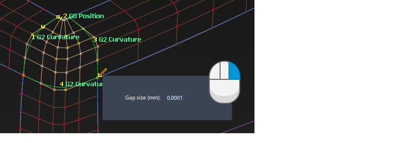
It is quite common for an arrow to appear at a corner, but for the square surface to still build successfully. The arrow is only a warning not an error, and is displayed for information only.
The arrow appears because the Square and Rail tools use an internal G0 tolerance for some computations which is a factor of 10 tighter than your chosen tolerance. The warning arrow will show any tolerance issues at this tighter value.
Right clicking the arrow displays the deviation between the boundaries.
Set a manual tangent angle along an edge
This manipulator only appears when you set an edge to Tangent Angle and the two adjacent edges are set to Free.
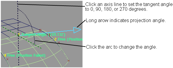
- Click an axis line to set the tangent angle to 0, 90, 180, or 270 degrees.
- Click an arc, then drag the mouse left and right to change the angle value, or type a number to set the value exactly.
- When you are finished, click the Go button.
Square workflows
Create a surface using corner points
A square surface can use the following combination of boundary curves/edges and free corner points:

Building from corner points:
- The first corner has to be specified using a snap mode (Alt, Ctrl or Alt+Ctrl).
- After the first point, click the remaining points (corners) in clockwise or counter-clockwise order.
- After the surface appears, you can move a corner locator by dragging it.
Combining Curves and points:
- If you mix curves and corners, you must click the curves first.
- To select a point ona boundary (instead of the boundary itself) use a snap mode (Alt, Ctrl or Alt+Ctrl). These work in UV mode, so CTRL will snap to an edit point or isoparm, and Alt will snap to halfway between.
Trouble-shooting continuity failure
There are several techniques to try when Square does not produce the intended results:
Experiment with the rebuild settings for each boundary. For example turn Rebld on for all boundaries with trimmed surfaces or curves on surface, and recalculate the surface.
Check the continuity of the surrounding surfaces if used as input boundaries. The square won't be able to achieve a hgigher continuity level than exists between the input surfaces or curves and surfaces.
If any of the boundaries are not required to be exactly G0 position, choose Free instead. This relaxes the constraint on that edge and allows other boundaries to have priority.
Use Explicit Control to override the degree and spans chosen by the square tool. Make sure that the continuity is evaluated (for example by turning on Continuity Check in the Control Options) as this is now under your control depending on your chosen explicit settings.
Set the Blend Type to Linear instead of Cubic.
Adjust the influence sliders to adjust the shape of the resulting surface.
Verify that the square surface doesn’t have a corner where the U and V edges are colinear.