 Panel Gap
Panel Gap uses the same techniques as the Fillet-Flange tool to create surfaces either side of a specified gap. Input surfaces and surface curves must be tangent continuous.
A gap can be created to split one set of surfaces, or to create a gap between two separate sets of surfaces.
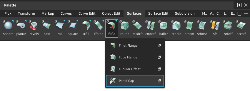
Access this tool from the Surfaces palette:
Panel Gap settings
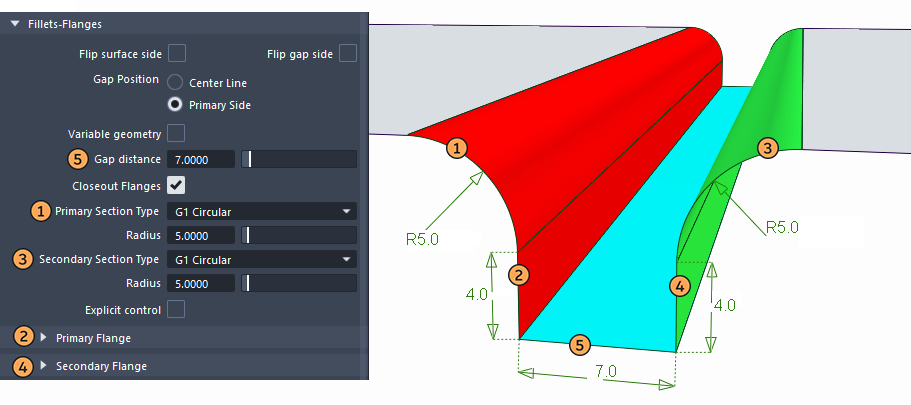
Fillets-Flanges
Flip surface side
Check or uncheck this box to reverse the direction of the fillets and flanges. This has the same effect as clicking the blue arrow that appears normal to the panel surface.
Flip gap side
Check or uncheck this box to switch the direction of the fillet in order to position the gap on the other side of the surface curve. There is a corresponding blue arrow on the model that you can click to switch the direction as well.
Gap Position
Specifies where the gap is located with respect to the input curves, as shown below.
Center line – Centers the gap over the input curves.
Primary side – Builds the primary geometry at the location of the input curves and positions the gap on one side or the other.

Gap distance
Specifies the initial width of the panel gap. The gap corresponds to the shortest distance between the primary and secondary rolled edges.
Closeout Flanges
Check on this box to create a ruled surface joining the bottom edges of the primary and secondary flanges (when both are present).
Primary / Secondary Section Type
Choose either G1 Circular, G1 Tangent or G2 Curvature for the continuity of the primary fillet with the panel surface. The standard settings for fillets are described in Surface Fillet
Primary Flange / Secondary Flange
Type
The options to control the primary and secondary flange are the same, with the addition of a third Type called Relative to Primary for the secondary flange.
Sweep angle – The flange us defined by a Sweep angle, which is the angle between the flange and the input surface.
Parting line – The flange is defined by the direction of a vector (specified through the Primary/Secondary Vector Options) plus a Draft angle.
Relative to Primary – This option only applies to the Secondary Flange. It lets you change the Draft angle or Sweep angle of the secondary flange relative to the first flange. This is useful to create a gap with zero width and coincident flanges, as shown below.

Sweep/Draft angle
Provides a slider to control the angle of the flange. The default is 90 degrees for Sweep angle, and 0 degrees for Draft angle.
Create flange
Determines whether or not a flange will be built off the edge of the fillet.
Length
Specifies the length of the flange, if Create flange is checked on
Panel Gap advanced settings
Evaluation
Gap check
Turn on this option to show a deviation comb, as well as minimum and maximum deviation at the gap location.
Additional options appear to let you control the deviation locator.
Closest point samples
The number of quills displayed on the deviation comb.
Comb scale
Increase this value to see small variations in the deviation comb.
Threshold
Acts as a tolerance, and is most useful in the case of a constant gap width. If the gap is within that value of the requested Gap distance, the deviation quill is green, otherwise it is red.

Here Gap distance = 50.0 and Threshold = 0.1
Variable geometry
When this box is checked on, you can click on the input surface curve(s) to position manipulators that allow you to vary the gap distance (default), the direction of the primary vector, or the direction of the secondary vector (see Create Manip below) along the length of the gap.
Create Manip
Only appears when Variable geometry has been selected.
Specifies the type of manipulator that is created when you click the input curve.
Gap – The gap manipulators control the width of the gap. They appear as straight lines across the gap.
Primary Vector – The primary vector manipulators control both the draft direction and the primary flange direction. These manipulators appear as purple arrows.
Secondary Vector – The secondary vector manipulators control the secondary flange direction. These manipulators appear as yellow arrows.
Using the manipulators to create a variable gap
When Variable geometry is checked on, you can control the width of the gap, or the direction of the primary and secondary flanges by placing and adjusting manipulators along the gap.
A label called Create Manip [Gap] appears on the model near the center of the input curve. Clicking on [Gap] toggles between [Primary Vector], [Secondary Vector], then back to [Gap]. This determines the type of manipulator that will be created when clicking the input curve. The behavior is the same as setting the Create Manip option in the control window.
Each manipulator consists of two handles, one at each end. Click on a handle to change its value (it turns white) or simply roll over it to see the value (it turns yellow). Hold Shift and click on a manipulator to remove it.
Only manipulators of the type indicated by the Create Manip label can be modified. Others are drawn in grey. The prompt line gives feedback while using the manipulator controls.
Gap manipulator
Click and drag the small circle to slide the manipulator along the curve, or type a parameter value on the keyboard and press
Enter.Click and drag the small triangle to change the gap distance at that location, or type a value on the keyboard and press
Enter.
The gap widths between the edge of the panel and the first manipulator, as well as between the opposite edge of the panel and the last manipulator, are constant. The width between any pair of interior manipulator is interpolated.
Vector manipulators
Clicking a primary or secondary vector displays full manipulator controls, including arcs for X, Y, and Z rotations, axes for alignment along X, Y or Z, and a small circle for unconstrained motion in all directions.

The primary and secondary vectors can be aligned to existing vector objects. Click on the arrow of a Primary Vector or Secondary Vector manipulator, then click an existing vector object to set the draft direction at the given location to that of the vector, or type three values (X, Y, Z) on the keyboard and press
Enter.For both Primary Vector and Secondary Vector manipulators, the vector direction between the edges of the panel and the nearest manipulator remains constant. Between any pair of interior manipulators, the vector direction is interpolated.
Panel Gap common parameters
Panel Gap has the following Surface Tool Common Parameters sections:
- Form Factor & Fillet Specify
- Explicit Control
- Range
- Surface Structure
- Control Options
Panel Gap workflows
Input Selection
Two methods can be used to create the fillets and flanges of the panel gap.
Selection of one or more tangent continuous surface curves. This provides all the required input to define the gap conditions.
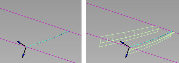
Additional selection of a set of tangent continuous surfaces (shown in yellow below), that may be offset from the primary surface(s), and which are used to build the secondary fillet and flange. Note that the Flip Gap Side arrow may need to be switched towards the second set of surfaces to allow the panel gap surfaces to build successfully.

Create the panel gap
Shift-select the Panel Gap tool
icon to open the control window.Pick a surface curve, or several tangent continuous surface curves (defining one side of the gap).
The curve is highlighted in green, and the surface turns pink.
Do one of the following:
- Click the Build button and go to step 5
- If you want to select adjacent surfaces from which to build the second set of fillets and flanges, click the Adjacent Surfaces button.
Select a set of tangent continuous surfaces (where the secondary fillets and flanges will be located) and click the Build button.
The surfaces turn yellow.
Click on the blue arrows, if necessary, to change the direction of the fillets/flanges or gap, and click the Build button.
Primary and secondary fillets and flanges are built. The panel surface is automatically trimmed to the edges of the fillets to create the gap.

Gap built along a curve-on-surface within a single panel surface
Modify options in the control window, and click Build again.
The four surfaces are recalculated.

After modifying fillet radii, flange angle and length, and gap distance.
Turn on Modify Primary Range and Modify Secondary Range, and adjust the extent of the panel gap with the sliders or manipulators if necessary. Click the Build button.
To create a variable gap, turn on Variable geometry, then click on the surface curve(s) to place gap manipulators, and adjust their position and width. You can also vary the direction of the primary (draft) vector, or secondary vector along the gap.

The fillets and flanges have construction history, so modifying your input curves will cause those output surfaces to update.
To modify the panel gap after exiting the tool, choose Object Edit > Query Edit and pick one of the output surfaces (fillets or flanges) to re-invoke the tool in the usual way.