 Round
Round
Creates rounded surfaces along edges and at corners where existing surfaces meet, and trims the input surfaces.
- The tool creates tangent or curvature continuous filleted surfaces and tangent continuous corner blends.
- When blending corners, you have the choice of different geometries, including single surface, three surfaces, triangular surface, and six surfaces with setbacks. You can also create mitred corners.
- The fillets can have a variable radius.

Access this tool from the Surfaces palette:
Related video
Round settings
Fillets

Continuity
G1 Circular - Creates a fillet with circular cross-section which is tangent to input surfaces.
G1 Tangent - Creates a fillet with tangent continuity to the input surfaces, with the option of using Form Factor setting to modify the profile shape.
G2 Curvature - Maintains curvature continuity with input surfaces.
Form Factor
This parameter lets you adjust the shape of the fillet. It specifies the ratio between the lengths of the innermost and outermost CV arms of the hull in the V direction of the fillet. Values range from 0.01 to 2.0. The smaller the value, the sharper the bend in the fillet. (This option is not available when Continuity is set to G1 Circular.)
Initial Radius
Sets the initial radius, at the manipulator locations along the edge, that is used to create the fillets. To edit the radius value after the fillets are created, you need to use the in-canvas Radius manipulators.
Corner Blends

Create Corner Blends
When on, all of the four settings beneath it are applied to the initial build of the Round surfaces.
When off, no corner is built and the four settings beneath are ignored. Use this if you want to contruct the corners yourself, using the Corner Blend tool for example.
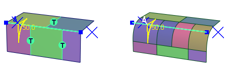
About Corner Blend Presets and the Manipulator Icons
The corner blend settings in the tool window specify the initial corner styles. Once built, the corner styles are displayed as individual manipulator icons on each corner. Clicking on an icon will toggle between all the possible choices for that corner geometry:
 None – Corner geometry is not created and fillets are not trimmed..
 Triangular surface – A single surface with one side of zero length.
 Three surfaces – Three regular (4-sided) surfaces.
 Trimmed Sphere – A portion of a sphere trimmed to the corner boundaries (G1 Circular only).
 Single Surface – One regular (4-sided) surface.
 With setbacks – Six or eight surfaces, with their edges extending into neighboring fillets.
 Blended – Mitred corner with a blended edge (when only two edges are selected).
 Sharp – Mitred corner (when only two edges are selected).
 Equal Radius Corner
Specifies the corner geometry when the radii specified along all three edges are the same. Click on the corner icon to cycle through the options, and click Build (or use Auti Rebuild in the Control Options).


 Unequal Radius Corner / Four Sided Corner
Specifies the corner geometry when the radii specified along all three edges are different, or a a corner where four edges meet.

 Mitred Corner
Specifies how two fillet surfaces meet at a mitred corner.

Control Options
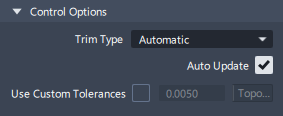
Trim Type
Automatic – Trims to the fillets and the corner blends.
Curves on Surface – Adds a COS for the corner blends.
Off – Does not produce curves-on-surface.
Auto Update
When selected, modifications to radius values and corner styles will rebuild immediately, without needing to hit the Build button on screen.
Use Custom Tolerances
Overrides the tolerances selected in Construction Presets ( Preferences > Construction Options ) and instead uses the specified custom tolerance. You can use the the Custom Tolerance parameter to test different tolerances.
Round common parameters
Round has the following Surface Tool Common Parameters sections:
- Continuity
- Form Factor
- Control Options
Viewport manipulators and buttons
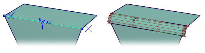
Radius manipulator

The radius manipulators appear when edges are selected for Round. They have two handles, as shown above.
- Click and drag the large arc to change the radius value or use the keyboard to enter a value.
- Click and drag the small triangle to move the manipulator along the edge or use the keyboard to enter an exact parameter value between 0 and 1.
Selecting manipulators:
- Click again on an edge to add an additional manipulator for a variable round.
- Shift-click to remove a manipulator.
- Ctrl-click to select additional manipulators and set them to the value of the first manipulator. Once selected they can all be changed simultaneously.
- Alt-click on a manipulator to select all manipulators set to the same value. Changing the radius value will change allthe selected manipulators.
Corner blend manipulators
Clicking on the corner manipulator icon will toggle it between all the possible choices for the corner geometry. If Auto Update is on in the Control Options, the corner will rebuild when you select each icon, otherwise use the Build button to update the Round geometry.
Buttons

Box Pick - Click this to choose Box Pick (box-selection) mode to locate all the edges that meet other surfaces. Edges that do not meet within tolerance, meet tangentially, or where the fillet would have to switch sides, are not selected. If Box Pick is active, individual edges cannot be selected until Accept is chosen (see below).
Pick Edges - Click this to select individual edges for rounding.

Accept - Click this to accept your current box selection. After clicking Accept, only the Pick Edges selection mode is available to select more edges. To return to Box Pick mode, click Undo All in the Round Control window.
Clear Selection - Clears your current selection when using Box Pick mode.

Build - Click this button to build the fillets and corner surfaces after all your edges and radii have been specified. You can still add or modify the radius values afterwards, and click Build again to modify the surfaces.
Revert - Click this button to remove the newly built surfaces. The radius manipulators are still present and can be modified. You can also add new edges, or delete edges by holding the Shift key.
Round workflows
Before you start...
Edges must be touching for the Round tool to apply a radius locator and then build the fillet surface. The default tolerance is set in Preferences > Construction Options under Tolerance >Topology > Topology Distance (see Preferences > Construction Options). You can also set the Custom Tolerance in the Round Control window to test different tolerances.
Make sure the surfaces don’t have internal tangent discontinuities (caused my multiple knots). These will cause the Round to fail.
If the surfaces meeting at the edge are tangent to each other at any point, or if the round would switch sides, the fillet will fail.

Using Pick Edges
Select the Round tool
icon.Make sure that the Pick Edges button is selected (bottom right-hand corner of the active view).
Click once on an edge to add a radius manipulator. Note that edges must have G0 Positional continuity to within your chosen tolerances. Continue adding manipulators to edges if required.
Click Build, or use the Auto Update option in the tool window.
You can continue to make modifications to the radius or corner manipulators, and use the Build button again, until you move on to the next tool.
To return to the Round and make modifications, use Object Edit > Query Edit. For some changes, you may need to use the Revert button first.
Using Box Pick
Select the Round tool
icon.Make sure that the Box Pick button is selected (bottom right-hand corner of the active view).
Drag-select across all edges. The Round tool locates all the edges that meet other surfaces. Edges that do not meet within tolerance, meet tangentially, or where the fillet would have to switch sides, are not selected.
If you make a selection error, click Clear Selection. Otherwise, confirm your selection by clicking Accept (space bar for shortcut if Accept is already highlighted).
If any edges need to be added or removed, the tool is now in Pick Edges mode. Radius values can be modified on individual edges and corner styles can be changed by clicking on the manipulators.
Click Build, or use the Auto Update option in the tool window.
You can continue to make modifications to the radius or corner manipulators, and rebuild, until you move on to the next tool.
To return to the Round and make modifications, use Object Edit > Query Edit. For some changes, you may need to use the Revert button first.
Edge Conditions
The Round surfaces will be built so that the input surfaces will trim. The Round surfaces will be extended to achieve this, and in some cases additional isoparms will be inserted.
To trim edges that don't require a radius value, but meet the radius surfaces, give those edges a zero value radius to have them included in the automatic trimming.
To delete a round surface
If the Round still has construction history, use Object Edit > Query Edit to activate, and either:
- Click Undo in the tool window
- Click the Revert button and then Pick > Nothing
If the Round has lost construction history:
- Pick the Round group and delete.
- Then use Surface Edit > Untrim to restore the primary surfaces.
- Use Pick > Curve-on-Surface and Delete to remove the left over C-o-S.
When primary surfaces don't trim
Occasionally there will be a trimming issue with a complex Round. In most cases this can be addressed by projecting curves-on-surfaces from the edges of the rounds and trimming the surfaces.
Creating variable radius rounds
You can add as many radius manipulators as you want to set the radius of the fillet at several points along the edge.
- The radius value will blend smoothly between two manipulators.
- The radius value will stay constant between a manipulator and an edge, when the manipulator is not at the end of the edge.
Use shift-click to remove a radius manipulator.
If two or more edges are tangent continuous, they are treated as a single edge. Creating a smooth variable radius fillet across the surfaces then requires only two radius manipulators (rather than one for each edge). However, the fillet will be made up of a separate surface for each edge.
