 Rail
Rail
Create a surface by calculating the area swept out by a generation curve moving along one or more rail curves. You can use one generation curve or blend between two or more generation curves.
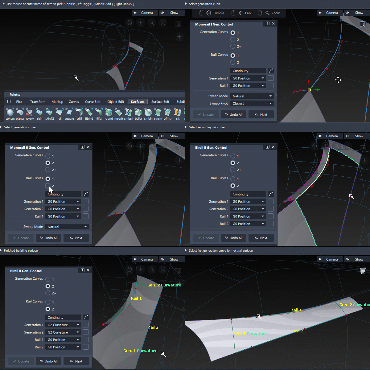
Access this tool from the Surfaces palette:

Related video
Rail settings
Bi-Rail and Mono-Rail were originally separate tools, but were merged because they both had the following common settings.
Generation and Rail Curves
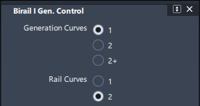
Choose the number of generation curves to be swept along 1 or 2 rail curves. If one set of curves is longer, then these are normally selected as the rail curve(s), and the shorter ones as the generation curve(s).
Follow the prompts to select the generation curves first, followed by the rail curves. If the surface doesn't build, read the prompt message to diagnose the problem, typically one of:
- First (second) gen. curve and Primary (secondary) rail must intersect.
- Rail curve has multiple interior knots. Try another SWEEP MODE or Rebuild Rails ON.
- Gen. curves must intersect rails at equal knot values for Rebuild OFF. Try Rebuild Rails ON.
- Combined rail curves exceed Max Surf Spans tolerance. (This normally means that the rail curves need to have Rebuild turned on, or smaller stretches of surface should be considered.)
- Gen curves picked out of order or gen curves cross (for 2+ gen curves only).
For 2+ generation curves, follow the prompt to select each gen curve in order, and then use the Go button to indicate that all the generation curves have been selected and the next selection will be the primary rail curve.
Continuity table and rebuild

The Continuity Table displays one row for each boundary. Use this to select the continuity and rebuild settings:
Use the title pop-up menus
 to adjust the settings for all 4 boundaries.
 Use the pop-up menu and checkbox
 on each boundary to adjust individually.
Continuity
Select the Continuity you want between each boundary of the rail surface and the adjacent surface. See Surface Tool Common Parameters for explanations of each continuity option.
Rebuild
The effect of turning rebuild on or off can be difficult to predict, and can sometimes make the surface parameterization worse rather than better.
Most users quickly experiment with different combinations to find the best result. The following are guidelines for finding the best settings for rebuilding the input boundaries:
Typically don't use Rebuild on a well-parameterized natural surface or curve input boundary.
Try using Rebuild On for trimmed edges.
Try using Rebuild On when opposite edges have different parameterization.
Rebuild On is is necessary for rail curves with multi-knots or CV weights, and recommended for generation curves with multi-knots or CV weights.
Rebuild Interior Gen. Curves (2+ gen curves only)
Rebuilds all interior generation curves when 2+ generation curves are used.
Curve Segments (1 generation curve only)
By default, a rail surface is built to the full length of the input curves.
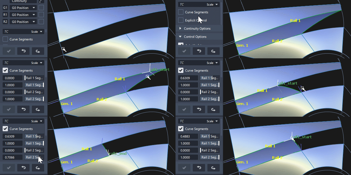
Use Curve Segments to display locators which can be dragged to change the start and end values (or enter values in the Segment boxes). UV snapping can be used: Ctrl for snapping to edit points or isoparms, Alt for halfway between.
Blend Control (2 generation curves only)
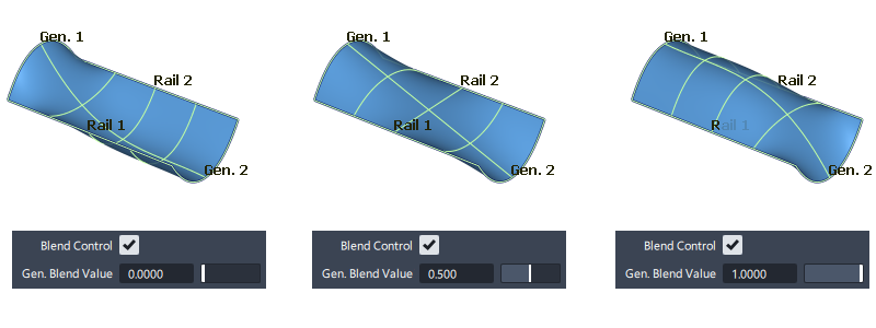
Blend Control modifies the influence of the generation curves over the rail surface shape.
Selecting Blend Control displays the Gen. Blend Value slider to control the midpoint of the blend between two generation curves.(the point where the influence of both generation curves is equal).
The default value is 0.5 which blends the two curves equally, so that the halfway point of the blend occurs at the midpoint of the rails.
Moving the slider towards 1 gives the Gen. 1 shape a stronger influence.
Moving the slider towards 0 gives the Gen. 2 shape a stronger influence.
The values 0.0 and 1.0 still blend the two curves a minimum amount.
Continuity Options
These options only appear if Explicit Control is turned off. (In practice Explicit Control is often preferred as a method of influencing the surface structure.)

Max. New Spans
Maximum number of spans the Rail tool can insert on each edge of the new surface as it tries to achieve continuity. If the Rail tool cannot achieve tangency without inserting more than the allowed number of spans, it displays an error in the prompt line.
Insert at Midpoint
When selected, insert extra edit points at the midpoint of the span with the largest continuity deviation. This is the default, and results in a better distribution of the isoparametric curves. When not selected, insert extra edit points at the location of the largest continuity deviation.
Colinear Options
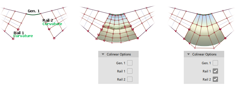
Select the boundaries where you want alignment with the hulls of the adjacent surface (when using G1 Tangent or G2 Curvature continuity).
Be careful not to use colinear on edges where the CV/hull flow would distort the rail surface being built.
Mono-Rail settings
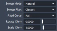
Sweep Mode

Natural – As the generation curve sweeps along the rail, it pivots to maintain the same angle relative to the rail curve.
Parallel – As the generation curve sweeps along the rail, it maintains its original orientation.
View (advanced) – As the generation curve sweeps along the rail, it only rotates in one plane, to maintain the visual angle between the generation and rail curves. Choose the plane from the Sweep Projection pop-up menu:
User – Type the X, Y and Z co-ordinates of the 3D vector in the View Plane boxes.
XY XZ YZ – Use a global plane (XY, XZ, or YZ) as the rotation plane.
Active – Take the rotation plane from the current view window.
Spine (advanced) – Use a spine curve to control the orientation of the generation curve as it sweeps along the rail. If the spine curve is not long enough to define the sweep surface, linear extension will be used to ensure coverage.
Sweep Pivot
For a mono-rail sweep, the generation shape must connect with the rail curve as it is swept.
If the gen. curve is drawn in the required starting position for the surface, touching rail curve, then the sweep pivots don’t need to be considered and the Closest setting will give the expected results:

If however the the positioning of the input curves is ambiguous, then two ‘pivot points’ are used to control the placement:
- Generation pivot – the attachment point on the gen. curve.
- Rail pivot – the attachment point on the rail curve.
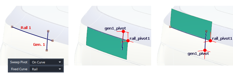
Use the pivots to specify the point on the free curve that should snap to the specified pivot on the fixed curve:
Sweep Pivot: Closest
The sweep pivots are calculated automatically by finding the closest points on the input curves. The pivots are not displayed on the screen and cannot be modified.
Sweep Pivot: On Curve
Sweep Pivots are displayed on the input curves, one on the Generation and another on the Rail. These can be positioned along each curve by dragging the locator. The pivot labels are only displayed once a pivot is selected.
When the sweep surface is built, the two pivot points become coincident, by moving either the gen. or the rail curve shape depending on the setting for Fixed Curve.
Sweep Pivot: Off Curve
Two Sweep Pivots are displayed, one approximately at the center of the Generation curve and another on the Rail curve. These can be freely moved anywhere in space. The pivot labels are only displayed once a pivot is selected.
The generation curve pivot can be positioned during the input sequence (followed by the Go button), before the rail surface is selected.
Both pivots can also be moved after creation while the surface is ‘live’, however this may lead to unpredictable results, in which case rebuild and position the gen pivot during the creation sequence.
Fixed Curve
This option determines which input curve is free and which is fixed if the curves are not touching.
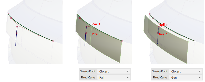
- Gen – The generation curve position is fixed, and the rail curve shape is moved.
- Rail – The rail curve position is fixed, and the generation curve shape is moved.
Rotate Xform (1 gen only)
The degree of rotation as the generation curve sweeps along the rail curve. (Default is 0)
For example, if Rotate Xform is 45, the generation curve will rotate a total of 45 degrees as it sweeps along the length of the rail curve. Use negative numbers to rotate in the opposite direction.
Scale Xform (1 gen only)
The scale factor as the generation curve sweeps along the rail curve. (Default is 1)
For example, if Scale Xform is 2, the generation curve will double in size as it sweeps along the length of the rail curve. If Scale Xform is 0.5, the generation curve will shrink by half as it sweeps.
Bi-Rail settings
Sweep Mode
This option is only available when at least one rail curve is being rebuilt.
Proportional – Rebuild the rail curves to create a surface with proportionally spaced spans and smooth parameterization based on the first rail curve.
View (advanced) – As the generation curve sweeps along the rail, it only rotates in one plane. This maintains the visual angle between the generation and rail curves. Choose the plane from the Sweep Projection pop-up menu:
User – Type the X, Y and Z co-ordinates of the 3D vector in the View Plane boxes.
XY XZ YZ – Use a global plane (XY, XZ, or YZ) as the rotation plane.
Active – Take the rotation plane from the current view window.
Transform Control
This option controls how the Rail Surface tool modifies the generation curves to stay on the rail curves during the sweep. It is only available when Rail Curves is 2.
Typical use:
Scale – (Default) Scale the generation curve proportionally, to the size necessary for the curve to stay on both rails.
Non-Prop Scale – Scale the generation curve non-proportionally, along the vector connecting the rail curves.
Advanced use (1 generation curve only):
Rotate no-Trim – The generation curve is kept rigid as it sweeps along Rail 1, while rotating to maintain contact with Rail 2. Rail 1 will typically be longer than Rail 2 to ensure that the swept shape doesn't 'fall off' as it is swept.
Rotate & Trim – This creates the same shape as Rotate no-Trim, but appears to be 'trimmed' to the second rail. In fact it is rebuilt to stay within the boundary of the second rail, and is not a trimmed surface.
Rail common parameters
Rail has the following Surface Tool Common Parameters sections:
- Continuity
- Explicit Control
- Control Options
Viewport manipulators and locators
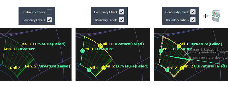
Boundary Labels and Continuity Check
The Boundary Labels are on by default, and they report whether the square surface has achieved continuity to within the Construction Tolerances.
The Continuity Check displays the achieved and failed continuity, using the same colors and decals as the Evaluation > Surface Continuity tool.
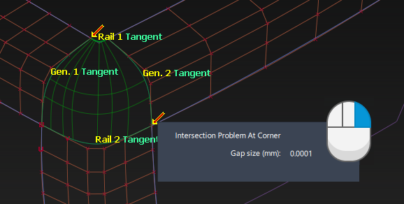
Warning Arrow
It is quite common for an arrow to appear at a corner, but for the rail surface to still build successfully. The arrow is only a warning not an error, and is displayed for information only.
The arrow appears because the Rail (and Square) tools use an internal G0 tolerance for some computations which is a factor of 10 tighter than your chosen tolerance. The warning arrow will show any tolerance issues at this tighter value.
Right mouse clicking on the arrow displays the deviation between the boundaries.
Rail workflows
Tips and notes
When using two or more generation curves, after you pick the first generation curve you can unpick it by clicking it. You can then pick a different first generation curve.
The Rail Surface tool can produce poor surfaces with long generation curves.
In these cases, try reversing the choice of generation and rail curves, and choose the shorter, simpler curves for the generation curves and long, winding curves as the rails.
The Spine sweep mode can be very tricky. If you have trouble with it, try the following:
Create a copy of the rail curve to use as the spine curve.
Turn on Create History and Auto Update in the Rail Surface Control window.
Reshape the spine curve in small steps and observe the effect on the surface.
After you start a surface in Natural, Parallel, or View mode, you cannot convert it to Spine mode.
What if the surface doesn't build
If the surface doesn't build after the input sequence, check the prompt line for an error message.
If modifications to the boundary curves cause them to stop intersecting (while construction history is on), the boundaries and isoparms of the surface are displayed with dashed lines and an error message is given in the prompt line history.
Check the following common issues:
You can’t create a surface along rail curves with sharp corners, CV multiplicity, or multi-knots. To remove multi-knots, turn on the Rebuild option for rail curves.
For Bi-rail, make sure your curves intersect. The Rail Surface tool tests whether curves intersect within the Curve Fit Distance tolerance in Construction Options. To change the Curve Fit Distance option, choose Preferences > Construction Options
What if the continuity fails?
- Check the continuity between any input surface edges.
- Use one of the methods below to try to improve the continuity achieved.
What if the resulting surface is too complex?
Experiment with turning on the Rebuild options for the curves used to create the surface.
Try using the Explicit control option, then manually choose how many spans the surface may have and what degree it should be in the U and V directions. Check the continuity results carefully as they may fail depending on your choices.