 Multi-Edge Blend
Creates a surface from two or more input edges that define a closed region.
Access the tool from the Surfaces tool palette:
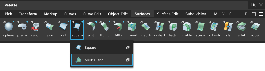
Multi-Edge Blend settings
Edge Split Type
Defines the seam positions of the multi blend surfaces on the selected edges, if no single surface is created.
- User Defined – Locate the seam positions individually by dragging the edge point handles.
- Flexure – The seam position is calculated from the arc length and the curvature of the edge.
- Arc Length –The seam position is set to the middle of the side with respect to arc length.
- Parameter – The seam position is set to the middle of the side with respect to the original parameter flow.
Edge Continuity
Defines the global quality of the transition across the selected surface edges and curves: G0 Position, G1 Tangent, or G2 Curvature.
If adjacent edges or curves are not connected to an edge with tangent continuity, the corresponding side will initially be set only to position continuity.
Seam Continuity
Define the continuity at the seams: G1 Tangent, or G2 Curvature.
Shape Factor
Controls the shape of the multi blend surface by means of a shape factor. If the Shape Factor option is not available, a value of 1.0 is used.
Cross Variation
Controls the calculation of transitions across the selected edges. It is only relevant for tangent or curvature continuous transitions. Use this option for better control point distribution within the created surfaces. It requires a higher degree for the calculation of a result with the best possible accuracy.
Inner Curvature
Forces the inner boundaries between surfaces to be G2 Curvature continuous, typically resulting in more complex surface geometry.
Star Point Modification
The star points are calculated automatically with the first calculation of the blend surfaces. After this calculation, you can change the points as follows:
- Automatic – The star points are calculated automatically.
- Planar – Move the star point on the blend surface by dragging the circle manipulator. The surface normal at the star point is preserved.
- Normal – Move the star point normal to the blend surface by dragging the arrow manipulator. The surface normal at the star point is preserved.
- View – Move the start point in the view by dragging the arrow manipulator.
U, V Degree
Allows you to specify a uniform degree for the creation of multiple surfaces or two different degrees for the creation of a single surface. If this option is inactive, the degree is determined internally depending on the input geometry and the algorithmic requirements. The created surfaces will always be single-span surfaces.
Single Surface
The multi blend can be created as a single surface. In case of a three-sided hole, a triangular surface is created, which due to system requirements must be subdivided into three rectangular surfaces. In the case of a four-sided hole, a rectangular surface is created. Only in this case is it possible to specify two different degrees.
Multi-Edge Blend common parameters
Multi-Edge Blend has the following Surface Tool Common Parameters sections:
- Control Options
Multi-Edge Blend workflow
Because each edge can consist of more than one tangent-continuous segment, you are required to hit 'Accept' once you have completed selecting one edge (even if it is only a single curve).
Select the Multi-Edge Blend tool and follow the prompts: select the curve(s) for the first edge and hit 'Accept'.
A minimum of two input curves are required, so select the second curve(s) for the second edge and hit 'Accept'.
A 'Done' button appears. If the two edges you have selected form an enclosed shape you can select 'Done' to finish selecting edges.
If you have another edge to select, ignore the 'Done' button and continue selecting.
For the third and subsequent edges, continue hitting the 'Accept' button to finish selecting an edge.
When all edges have been selected click on the 'Done' Button. The continuity settings for the edges will be displayed on the geometry and can be modified.
A 'Build' button now appears, click on this to build the surface.
If you are working with the Control Window open, make any required changes and hit the 'Update' button to rebuild the surface. Alternatively use Auto Update in the Control Options.