Primitives (NURBS)
![]()
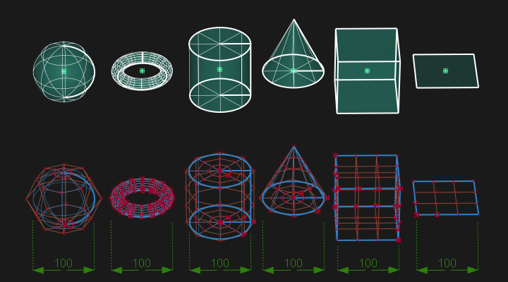
The following NURBS primitives can be created:
 Sphere
  Torus
Torus  Cylinder
  Cone
Cone  Cube
Cube  Plane
Plane
- Place a primitive by clicking in the scene or by entering a co-ordinate position in the prompt line.
- Primitives are created at a default size of 100 units. Use the manipulator, transform tools or the Information window to change these sizes.
- The pivot point for the primitive defaults to the center of the geometry (except for the cone which has the pivot at the centre of the base).
- Primitives can be sculpted by displaying the CVs and using the Pick and Transform tools.
- Cube is a group of 6 surfaces
- Cylinder and Cone will be a group if end-caps are selected in the options.
- Sphere, Cylinder, Cone and Torus will be periodic surfaces when 360 degree sweep is selected.
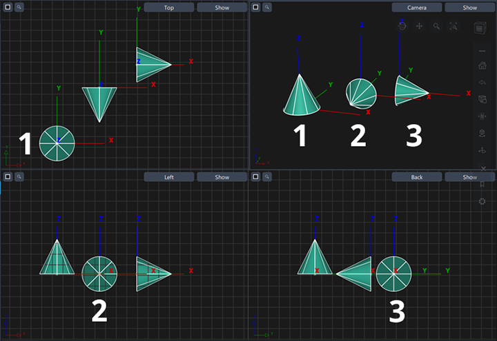
The view window that is used for placement will affect the orientation and the local axes of the primitive as shown below:
- Shows a primitive cone placed in the Perspective view and the Top view window, or by typing a co-ordinate in the prompt line.
- Shows a primitive cone placed in the Left or Right view window.
- Shows a primitive cone placed in the Front or Rear view window.
Access the NURBS primitives tools from the the Surfaces Palette:

Working with the manipulator
- Drag an arrow to move the object along an axis.
- Click an arrow, then drag the star at the center of the manipulator with the mouse buttons to move the object freely.
- Drag a cube to scale the object along an axis.
- Click a cube, then drag the cube at the center of the manipulator to scale the object uniformly.
- Drag a sphere or arc to rotate the object around an axis.
- Click a sphere, then drag the sphere at the center of the manipulator with the mouse buttons to rotate the object freely.
See Also
Sphere Primitive Options
Sphere Type
- Surface – Create sphere from a single NURBS surface.
 Self Inflated Cube - Create a sphere from six quartic single span NURBS surfaces stitched into a shell.
- Shell Tennis Ball – Create a sphere from two interlocking surfaces stitched into a shell like a tennis ball.
- Shell No-Pole – Create a sphere from eight surfaces stitched into a shell.
Object Degree
The degree of the surfaces used to create the sphere. Choose 1 (linear) through 7.
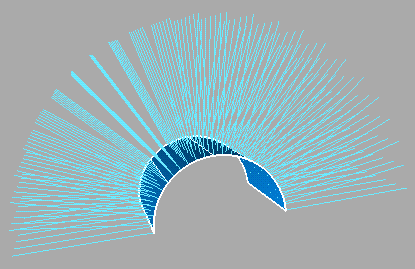
Sweep
The degrees of rotation around the center of radial primitives.
For example, if you enter 180 degrees in the sphere tool, Alias creates a hemisphere.
Sections
The number of subdivisions (spans) on the surface.
The default is 8. At least 4 subdivisions are usually needed to create a workable primitive shape. It is not usually necessary to use more than 20 subdivisions.
Torus Primitive Options
Sweep
The degrees of rotation around the center of radial primitives.
For example, if you enter 90 degrees in the torus tool, Alias creates a quarter torus.
Size
Size can be either Absolute or Relative, and determines which of the following parameters can be set.
Major radius
The distance between the center of the ring and the center of the tube. This option is only available if Size is set to Absolute.
Minor radius
The radius of the tube. This option is only available if Size is set to Absolute.

Ring Thickness
The diameter of the ring relative to the diameter of the entire torus. This option is only available if Size is set to Relative.
As the ring thickness approaches 0.5, the hole gets smaller. At 0.5 the torus has no hole. See the following figure.

Cylinder Primitive Options
Degree
The degree of the surfaces used to create the cylinder. Choose 1 (linear) through 7.
Sweep
The degrees of rotation around the center of radial primitives.
For example, if you enter 180 degrees in the sphere tool, Alias creates a half cylinder.
Spans
The number of spans that run along the cylinder length.
The default is 8. At least 4 spans are usually needed to create a workable primitive shape. It is not usually necessary to use more than 20 spans.
Caps
Creates periodic surfaces to close the ends of the cylinder. Choose 0 (no caps), 1 (a cap at the bottom only), or 2 (caps at both ends).
Cone Primitive Options
Degree
The degree of the surfaces used to create the cone object. Choose 1 (linear) through 7. The default value is 3.
Sweep
The degrees of rotation around the center of radial primitives.
For example, if you enter 180 degrees, Alias creates a half cone.
Spans
The number of spans that run along the cone length.
The default is 8. At least 4 spans are usually needed to create a workable primitive shape. It is not usually necessary to use more than 20 spans.
Caps
Creates a periodic surface to close the open end of the cone.
Cube Primitive Options
Object Degree
The degree of the surfaces used to create the cube. Choose 1 (linear) or 3 (cubic).
Plane Primitive Options
Object Degree
The degree of the surfaces used to create the plane. Choose 1 (linear) or 3 (cubic).
About What NURBS surfaces cannot do
Because of the underlying representation of NURBS surfaces, there are some things they cannot model:
Topologies that are not equivalent to a rectangular sheet.
Spheres, cones, tori, and triangles can all be built from sheets by attaching or collapsing sides. But more complex shapes, for example a star shape, cannot be represented with a simple NURBS surface. To get a complex surface outline, you must use a trimmed surface or a network or collection of four-sided surfaces.
Holes.
To create a hole in a surface, use a trimmed surface.
Surfaces that cannot be mapped with regular U and V coordinates.
For example, you can model the shape of a Mobius strip, but the surface will have a seam.
About normals and surface orientation
Normals are imaginary lines perpendicular to each point on a curve or surface.
The direction of U and V isoparms on a surface determines the direction of the surface normals, according to the right-hand rule. This rule states that if the thumb of your right hand points along U, and the forefinger along V, then your middle finger, bent at a right angle from the first two, points along the surface normal.
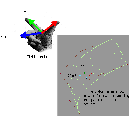
Normals are an indirect indicator of the shape of a curve or surface. Since they are always perpendicular to the curve or surface, the way normal lines point toward or away from each other can reveal subtle curvature.
The orientation of a surface—the direction it is facing—is distinct from the U and V directions (tangents) for modeling/evaluation purposes. Changing the orientation of a surface preserves construction history and does not affect texture mappings.
All tools (Ambient Occlusion, Draft Evaluation, Parting Line, Offset) use orientation, rather than surface normal, to determine which way the surface is facing. We provide three tools in the Surface Edit > Orientation submenu to modify the orientation of surfaces. These tools flip the surface without affecting its U and V directions. Hence the orientation might correspond to the same direction as the normal (default), or the opposite direction.
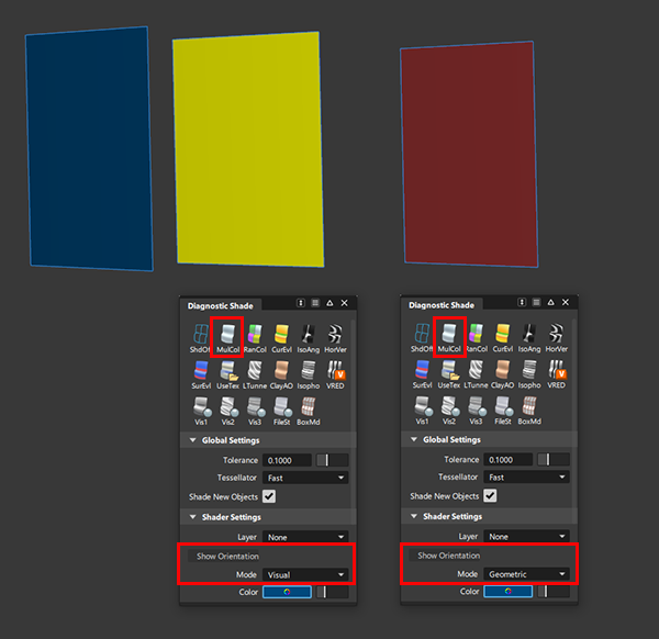
The Multi-Color mode of Diagnostic Shading uses yellow and red colors to show the orientation of the visual normals and geometric normals. When Show the Orientation Mode is set to Visual, yellow means that the back of the surface is facing the viewer. When set to Geometric, red means that the geometric normals are reversed. Once again, this orientation is independent from U, V, and surface normal, as shown in the following image.
If the U or V direction of the surface needs to be modified, this can be done with a separate tool (Surface Edit > Reverse Surface UV) which affects the surface normal but does not affect the orientation of the surface. This might be necessary, for example, to reverse a texture mapping.
When exporting a file, the surface orientation information is translated assuming the file format can support it in some way.
About shells
Shells are a special type of surface or collection of surfaces you can use for special modeling operations, or for export to solid modeling packages.
Shells are collections of adjacent NURBS surfaces. Every surface stitched into a shell must meet the edge of another surface in the shell at some point.
Shells are stored as a single node in the DAG.
Shells can be open or closed. For closed shells, the normals should always point outward. This is necessary for the Boolean operations.
The main uses of shells are:
To improve data transfer to some CAD packages.
Some CAD packages deal with shells much better than normal trimmed NURBS surfaces.
To prepare for Boolean operations.
The Boolean tools (Shell subtract, Shell intersect, and Shell union) only work on shells. Often you simply stitch surfaces into shells, apply a boolean operation, then unstitch back into surfaces.
To check adjacencies between surfaces.
Surfaces can only be stitched into shells if they are within an adjacency tolerance.
If the tolerance is set correctly, you can easily check whether a group of surfaces will export or build properly by checking whether they stitch together into a shell.
To identify open edges in stitched shells:
Use the Query Edit tool
 to check for open edges in shells. Red arrows clearly mark gaps in the shell.
Shells have the following limitations:
Depending on the options in the Shell stitch option window, a stitched shell may not match the original surfaces exactly.
In this case, unstitching does not produce surfaces that match the originals exactly either.
You cannot edit CVs of a shell. If you need to reshape the surface of a shell, you must unstitch the shell.
You cannot use the isoparametric curves of shell surfaces as input for other tools.
You cannot maintain continuity with a shell in tools such as Square and Rail Surface.
You cannot create fillet surfaces on shells or between shells and other surfaces.
If you stitch an object, then scale it, then unstitch it, you not be able to restitch the object. This is because the scaling operation can increase the gaps between surfaces, thereby causing any subsequent stitch operations to fail (within the current tolerance settings). In this case, scale the object before you first stitch it.
About rational and non-rational geometry
Non-rational geometry is a sum of polynomials. Rational geometry is a ratio of sums of polynomials. Rational geometry is considerably more complex mathematically. Therefore:
- It may not be transferable to downstream CAD packages that can’t deal with complex descriptions
- It can be slower to manipulate when modeling.
The following tables lists the differences between the two types of geometry.
| Nature | Pros | Cons |
|---|---|---|
| Non-rational | More flexibility for transformations.Faster. | Sacrifices some precision for modeling flexibility. |
| Rational | Precise geometry (that is, exact conics). | Weighted CVs not supported by many CAD packages. Weighted CVs harder to manipulate.Creates multi-knots. Slower to display. |
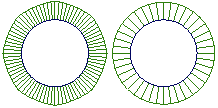
This illustration shows two circles drawn with the two types of geometry.
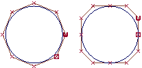
- The circle on the left is a non-rational curve with CVs that are all weighted equally. To have a non-rational curve, all weights must be 1.0.
- The circle on the right is a rational curve with different weights applied to the CVs, and multi-knots.
You can see the difference in two ways:
If you attach a radius measurement to the circles, the non-rational circle is not a perfect circle (although it is close): it has different radii depending on where you measure. The rational circle is a perfect circle.
Attach curve curvature combs to the circles. The curvature on the non-rational circle on the left varies. The curvature of the rational circle on the right is constant.