 Multi-Surface Draft
The MS-Draft tool extrudes flange surfaces from curves or surface edges in a chosen direction, optionally adding a draft angle and a crown shape.
In the Draft mode the direction of flange is determined in the XYZ space.
In Normal mode typically surface edges, isoparms of curve-on-surfaces are used as inputs, and the flange direction is determined by the normal directions of the surface they belong to.
Access the tool from the Surfaces Palette:

Related video
MS Draft settings

Type
Draft - Creates surfaces from curves or surface curves that all extrude in a vector direction. Adding a draft angle adjusts the direction of the surfaces 'outwards' or 'inwards' from the vector direction, to allow for extraction from a mold, or for design purposes.
Normal - Creates surfaces from surface curves that extrudes in the direction of the normal of the underlying surface(s). Adding an angle value adjusts the direction of the surfaces 'outwards' or 'inwards' from the normal direction.
Draft Angle/Angle + Flip Angle
When the Angle value is zero, the surfaces follow the Draft or Normal direction.
Adding an angle value modifies the surface direction equally in all directions. Use the Flip Angle button to switch between negative and positive angles. (This has the same effect as manually changing the numerical entry with a '-'.)
Length
The length of the flange surface from the input curves or surface curves.
Length Mode
Defines which distance the flange Length represents.
Default – The flange is built to the Length value specified.
Projected – The Length value is used to calculate an offset distance from the input curve, and the flange is built to that distance. If the draft angle is zero, then the default and projected values will be the same. If an angle is applied, then the true length of the flange will be different to the Length value specified.

Double Sided + Single Surface
Turn Double-sided on to build draft surfaces on both sides of a curve simultaneously. By default two sets of surfaces are built either side of the input curve. Select the Single Surface option to create a single surface instead.
Intersect Flanges + Trim / Trim Convert
Select this option to handle corner conditions when two flange surfaces meet. The flanges are extended and trimmed to their intersection so they join properly at corners. You can choose to Trim or Trim Convert the flanges.
Flip Surface
Reverses the direction of the built surface(s).
Viewport manipulators
The following settings can be modified interactively using the manipulator:
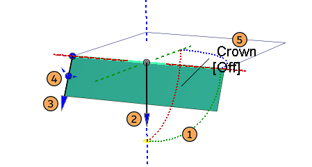
- Draft vector direction - (Type: Draft only.) Standard vector manipulator (See Surface Tool Common Parameters for details)
- Flip surface - Click on the arrow head to flip the surface.
- Length - Click and drag on the flange arrow to adjust interactively. Click to highlight and type in a value in the prompt line for numerical input.
- Angle - Click and drag on the circle to adjust interactively. Click to highlight and type in a value in the prompt line for numerical input.
- Crown Mode and Value - See Surface Tool Common Parameters.
Enter numerical input at the prompt line.
Adding manipulators for variable angle or length values
Additional manipulators can be added using a Shift-click on an input set that doesn't have any tangent breaks. These can be used to create variable angle and/or length MS Draft surfaces.

To work with additional manipulators:
Shift-click the input curve to add manipulators.- Move a manipulator along the curve by dragging the dot at the base of the manipulator.
- Remove manipulators by shift-clicking them.
- Each arrowhead and circle can be clicked to highlight, and a numerical value entered in the prompt line.
- Using the 'flip surface' arrowhead will flip all the manipulators.
MS Draft advanced settings for Type: Draft
Angle Calculation
3D Rotation – (Default) An accurate calculation using an envelope of cones to determine the direction of the flanges. This gives more accurate results for injection molding, but works best for small draft angles. With large angles the flange surfaces can get distorted, in which case switch to the 2D rotation method.
2D Rotation – The draft vector is just rotated out of the draft/tangent plane. This method is more stable mathematically, and does not break down for large angles. The flanges may not be accurate for molding requirements, so should be checked using the Surface Evaluation diagnostic shader.
To Surface
The Length setting in the control window is disabled, and the flange length is determined instead by selecting a target surface (or surfaces). This acts as a limit to the extrusion length of the draft surfaces.
After selecting the curves or surface edges/curves, you will be prompted to hit the Accept button (to complete curve selection), and then to select the bounding surface(s).
Radial
Selecting Radial orients the draft radially.
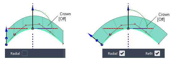
Refit
The Radial option creates a variation of the original draft surface. However, the radial surface does not follow the direction of the draft vector, so some radial draft surfaces may not meet the draft requirements. (The surface will fail the draft angle check in the Surface Evaluation diagnostic shader. The larger the angle between the default non-radial draft surface and the radial draft surface, the more likely the draft check will fail.)
To create a radial draft surface that satisfies the draft requirements, the Refit option attempts to refit the radial surface to the original draft surface, while still following the radial directions. It changes the radial draft surface to degree 2 in the draft surface length (V) direction, then aligns the upper row of CVs on the radial draft edge to the default non-radial draft surface, creating a crown. The resulting radial surface is closer to the original and produces better results when checking it with the Surface Evaluation diagnostic shader.
MS Draft advanced settings for Type: Normal
Flange from Curve
The default setting is off, in which case only a surface edge, isoparm or curve-on-surface can be selected for the Normal type, and the direction will be taken from the surface to which they belong.
Selecting Flange from Curve allows a free curve to be used instead, and the normal direction determined by choosing a surface, with one of the options:
From Surface - The direction of the flange will be taken from the surface normals of the selected surface, and the length will be specified using the Length value.
To surface - The length and direction of the flange will be taken from the surface normals of the selected surface. (The Length value in the Control Window will be disabled.)
After selecting the input curves you are prompted to select the surface to use for the normal direction.

Orientation Vector
The orientation vector allows adjustment of the edges of the flange surface(s). Use the manipulator to select a direction, or choose a vector in scene.

MS Draft common parameters
Surface Tool Common Parameters
Multi-Surface Draft has the following Surface Tool Common Parameters sections:
- Crown
- Axis & Vector Option
- Explicit Control
- Flow Control and Modify Range
- Surface Structure
- Control Options
In addition to the standard settings, MSDraft has the following specific settings.
Explicit Control Options : Fitting Method
Surface UV – Follows the U or V parameterization of the underlying surface. If this fails, then the COS is fit using the Curvature method.
Chordal – Fits based on the arc length. Each parameter step corresponds to an equivalent step in 3D. If the Segmentation Option is Bezier, Alias tries to produce equally spaced CVs.
Parameter – Matches the parameterization of the COS.
Curvature – Fits based on the arc length and curvature. Places more CVs in areas of higher curvature.
Blend – A hybrid of the Surface UV and Chordal fitting methods. A UV to Chordal Influence value of 0 is equivalent to using the Surface UV method. A value of 1 is equivalent to using the Chordal method. For values in between, the point distribution is a geometric mean between the two types.
Pick Mask
These options let you choose what types of curves are selectable as input. This is especially useful when using box selection.
Surface Isoparm - Check this option to make surface isoparms selectable as input.
Surface Trim Edge - Check this option to make surface trim edges selectable as input.
Curve - Check this option to make free curves selectable as input. This option only appears when Type is set to Draft.
Curve-on-surface - Check this option to make curves-on-surface selectable as input.

Control Options
The following option is specific to MS Draft.
- Tangent Angle Maximum - This option is only available when Inter Surface Continuity is checked on. It is used to exclude "corners" from the check. If, at any check point along a shared boundary, the angle between surface normals is larger than this value, then tangent continuity is not reported along that boundary. The default is set to 30.0 degrees.
Multi-Surface Draft workflows
Use the Multi-Surface Draft tool to create surfaces from a set of curves or surface curves.
Create Draft surfaces from a set of curves
Create one or more surfaces from a set of profile curves, along a pull direction.
Shift-select the Multi-Surface Draft tool
icon.In the control window set Type to Draft, and choose a pull direction from the Draft Vector Options.
In the Pick Mask section, turn off everything except Curve, so only free curves will be selectable as input.
Box-select all of your curves. The curves can be disjoint (non-touching), G0 (position continuous) or G1 (tangent continuous). You can also pick the curves individually if you want.
The Multi-Surface Draft manipulator appears.
Click the Build button.
The draft surfaces are built.

Do any of the following:
- Change the pull direction by choosing a different draft vector option or by using the pull direction manipulator.
- Change the Draft Angle and Length of the surface(s) through the control window or by using the manipulator.
- Turn on Explicit Control to adjust the control point layout and spans in the U direction.
- Turn on Double Sided to make the surface(s) extend on both sides of the curves.
- Turn on Intersect Flanges to automatically extend and/or trim the draft surface(s) at corners (where the original curves share endpoints).
- Turn on Modify Range and use the Start/End sliders or arrow manipulators to change the extent of the draft surfaces.
Click Update again to update the surface(s), or turn on Auto Update.
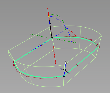
Double-sided draft surfaces with height = 30 and draft angle = 15.
You can add or remove curves from the selection, while in the tool, by clicking them.
Create Flange surfaces from curves of an existing surface
Create one or more surfaces from a set of surface curves, either along a pull direction, or at an angle relative to the original surfaces.

Double-click the Multi-Surface Draft tool
.In the control window:
- Set Type to Normal to create a flange-like surface, or Draft to create a draft surface.
- In the Pick Mask section, turn on the types of curves you want to select as input (Surface Isoparm, Surface Trim Edge, and/or Curve-on-surface).
- Set Surface Type to Single surface if you want to create a single flange or draft surface.
- Check on Auto Update.
Click or box-select all your curves. The curves can be disjoint (non-touching), or continuous.
As each curve is added, it is highlighted, and a flange surface is built. A single flange surface is created no matter how many surface curves you have selected.
 Note: Only G1 (or greater) input curves allow you to create a flange or draft surface of variable height or angle (using multiple manipulators).
If you set Type to Draft, you will also need to select a pull vector to specify the initial direction of the surface. (Use the Draft Vector Options or use Construct Vector tool to create a vector object).
Use the manipulator(s) to adjust the flange/draft surface’s length or angle (see below).
You can add or remove curves from the selection, while in the tool, by clicking them.
Set the angle or length at a point along the surface
Use the Multi-Surface Draft tool manipulators to change the Length and Angle, and to reverse the direction of the new surface(s).
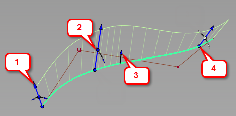
- Drag the arrow head to change the length of the surface.
- Drag the dot at the middle of the manipulator to change the Angle/Draft Angle of the surface.
- Click the Flip arrow head to reverse the surface direction.
Shift-click the input curve to add manipulators. Move a manipulator along the curve by dragging the dot at the base of the manipulator. Remove manipulators byShift-clicking them.
Set the pull direction with the manipulator

- Click an axis line to set the pull direction.
- Click the pull direction arrow to reverse its direction.
- Click one of the arcs, then drag the mouse left and right to change the pull direction.
- Click the free rotation handle to rotate freely in all directions.
- Click an existing reference vector to align the manipulator with it.