Use this procedure to change the regular window and corner window sill dimensions in the Sill Plan display representation.
You must use a display representation for a window that has a sill. You can turn on the Sill Plan display representation in addition to the Plan display representation.
- Click
 .
. 
- Expand Architectural Objects, and expand Window Styles.
- Select the style you want to edit.
- Click the Display Properties tab.
- Select Sill Plan for Display Representations, and select Style Override.
- If necessary, click
 .
. - Select the Window tab or the Corner Window tab.
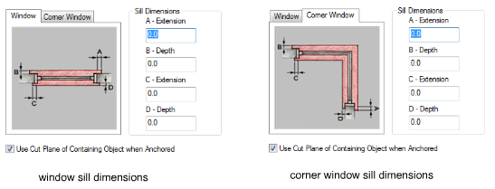
- Under Sill Dimensions, enter the sill extension and depth dimensions.
Sill components A and B are for the swing or outside of the window. Sill components C and D are for the interior side.
Note: For corner windows, A-Extension and B-Depth are applied to the anchored wall; C- extension and D- Depth are applied to the non-anchored wall. - If you want to use the cut plane of the wall for anchored windows, instead of using the cut plane of the window, select Use Cut Plane of Containing Object when Anchored.
- Click the Layer/Color/Linetype tab.
- Under Visible, click the icons to turn on visibility.
- Click OK twice.