You can create elevations of the building models in your drawings by first drawing an elevation line and mark, and then creating a 2D or 3D elevation based on that line. You can control the size and shape of any elevation that you create, and you can update an existing elevation when the objects included in the elevation are modified. 2D elevations are created with hidden and overlapping lines removed. You can control the appearance of 2D elevations by applying rules that are controlled by the style and display properties of the 2D elevation.
Elevation Line and Marks
The elevation line defines the extents of the elevation view of your building model. Elevation lines can be straight or jogged. You can also specify the length and the height of the area defined by the elevation line. Elevation marks, which typically contain a letter or number and indicate the direction of the elevation, appear at each end of the elevation line.
After you draw the elevation line, you create an elevation object from the line.
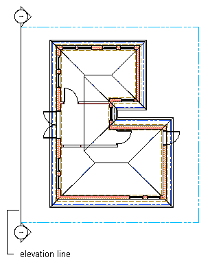
Viewing the elevation line and mark
2D Elevations
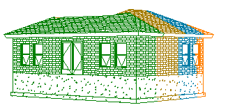
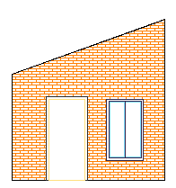
2D elevations are created by drawing an elevation line in front of a number of objects and then creating a 2D elevation object from them. The elevation object is drawn without hidden and overlapping lines. You can edit a 2D elevation by changing its object display properties or its style display properties. The 2D elevation style lets you add display components to the display representation of the elevation and create rules that assign different parts of the elevation to different display components. You can control the visibility, layer, color, linetype, lineweight, and linetype scale of each component. You can also assign a material, such as a brick or concrete hatch, to individual components of the object or the style. Furthermore, you can use linework editing commands to assign individual lines in a 2D elevation to different display components, and merge geometry into a 2D elevation. You can dimension 2D elevations.
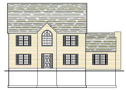
2D building elevation
3D Elevations
3D elevations are created by drawing an elevation line in front of a number of objects and then creating a 3D isometric elevation object from them. 3D elevations do not use styles. However, you can control the display of subdivisions within 3D elevations. Using the Hidden Line Projection command, you can create 2D hidden line projections of any view of the 3D elevation that you can explode and edit or hatch.
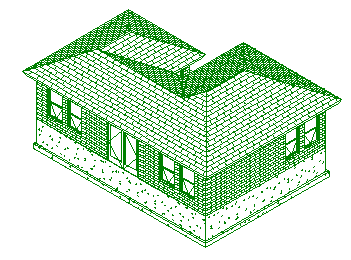
3D elevation in 3D view
Elevation Subdivisions
A 2D or 3D elevation object can have a number of subdivisions partitioning the elevation object. This feature is useful when you want to create a perspective view of the object, in which the parts that are closer to the viewer are drawn with darker and stronger lines, and parts that are farther off are drawn lighter.
3D elevation with subdivisions in perspective view
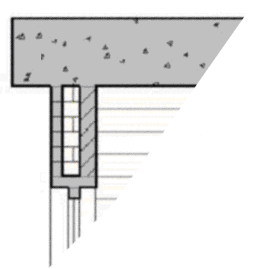
Live Section View
A live section view is a special view of a 3D section where the objects that are sectioned are not converted to a 3D section object, but remain in the drawing as objects. The parts of the objects within the bounding box of the section line keep their individual display components while the parts of the objects outside of the section line can be displayed or hidden. To control the appearance of the object parts outside of the section line, you need to assign a material to the sectioned objects.
When you render a live section, you can show the outside part as a half-transparent addition, for example.
You can use the live section view in an elevation in order to clip out just the region you need momentarily and to focus on that specific area. This can accelerate performance and make working with the building model easier.
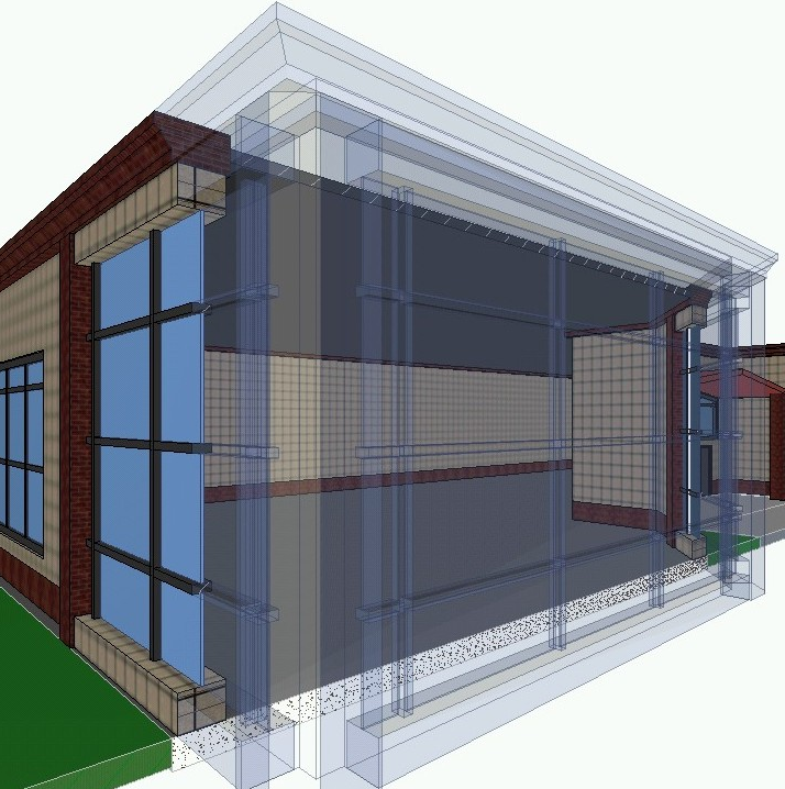
Rendered live section view with transparent body component
Materials in Elevations
In AutoCAD Architecture 2024 toolset, you can assign materials to different components of an object. These materials are displayed when you create a 2D or 3D elevation object. You can specify whether to use the display properties of the materials or the display properties of the elevation object.
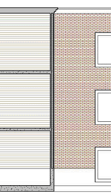
2D elevation with different surface hatches
AutoCAD Architecture 2024 toolset provides a large number of predefined materials for all common design purposes. You can use these predefined materials or modify them to your special designs. You can also create your own materials.
Subdivisions in 2D Elevation Styles and Materials
When you are creating subdivisions in your style, you usually want the objects in them to be visually distinct from other subdivisions. When you have assigned materials to the objects, you can set the 2D elevation style so that it uses the hatch pattern from the material, but uses the color and linetype from the subdivision display properties.
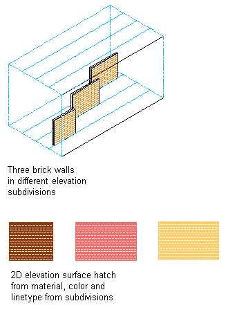
Elevation subdivisions with assigned surface hatching
Material Boundaries in 2D Elevations
Material boundaries allow you to erase or limit portions of a 2D elevation:
- Limit the amount of hatching to produce cleaner construction documents.
- Highlight a region in an elevation.

- Mask out a portion of an elevation so that more detail can be drawn.
- Crop an irregular-shaped portion of an elevation.