Use this procedure to convert a closed polyline to a single slab or roof slab that has the properties of the tool you select. You can edit these properties after the object is created. The first line drawn in the polyline becomes the baseline edge of the slab or roof slab.
Creating slabs or roof slabs from polylines is useful when you need to create a complex shape or one with curved edges. The smoothness (tessellation) of curved edges is controlled by 2 AEC display resolution settings called Facet Deviation and Facet Maximum. Beginning with Autodesk Architectural Desktop 2007, you can adjust these settings after the slab or roof slab is created. Also, the individual segments or facets making up a curved edge are no longer treated as separate edges; each arc on the perimeter of a slab or roof slab is treated as a single edge.
- Draw a closed polyline of the desired shape in the location where you want to place the slab or roof slab.
- Open the tool palette that contains the slab or roof slab tool you want to use.
(You may have to scroll to display the desired tool.)
- Right-click the tool, and click Apply Tool Properties to
 Linework and Walls (or Linework, Walls and Roof, in the case of roof slab tools).
 - Select a closed polyline, and press Enter.
- Enter y (Yes) to erase the polyline, or n (No) to keep the polyline in the drawing.
- Specify a mode:
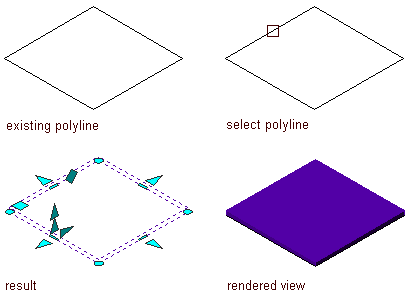
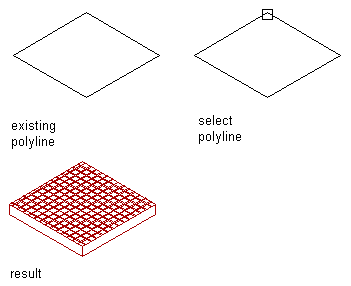
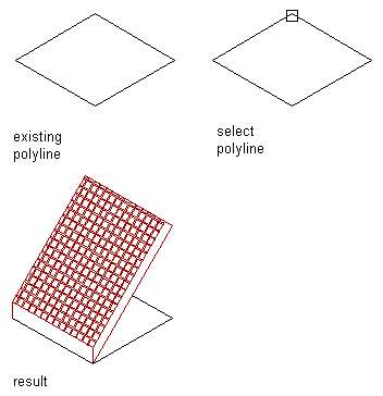
If you enter d (Direct), the polyline vertices become the vertices of the slab or roof slab perimeter. Any slope value specified in the tool properties is ignored.

Converting a polyline to a slab using the direct mode

Converting a polyline to a roof slab using direct mode

Converting a polyline to a roof slab using direct mode and adding a slope angle
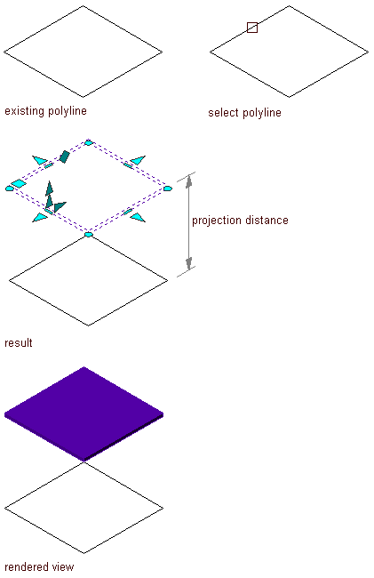
If you enter p (Projected), you are prompted for the base height of the slab or roof slab. The X,Y coordinates of the first polyline vertex are projected to a Z value of the base height. This establishes the insertion point.

Converting a polyline to a slab using the projected mode
- If you specified Projected mode, enter a value for Base Height.
- Specify a slab justification method:
If you want to align the slab or roof slab… Then… top with the polyline (or base height, when using projected mode) enter t (Top). center with the polyline (or base height, when using projected mode) enter c (Center). bottom with the polyline (or base height, when using projected mode) enter b (Bottom). slopeline with the polyline (or base height, when using projected mode) enter s (Slopeline). Note: This justification is used only for inserting a slab or roof slab and is not retained as a parameter of the inserted object. - Edit the properties of the slab or roof slab in the Properties palette, if needed. For example, you can add a slope angle.