You can use the Display tab of the Properties palette to change the display property settings for a selected object in the current display representation. You can change settings for properties that apply to the object as a whole (such as Cut plane height), as well as settings for the object’s individual display components (such as Color, Layer, and Linetype for a hatch component).
You can also specify whether your changes will apply to:
- all objects of the selected type (drawing default)
- all objects of the same style as the one to which the component belongs (a style override)
- only the selected object (an object override)
You can also apply your changes to other display representations that use the same display component to draw the selected object.
- If necessary, open the Properties palette using any of the following methods:
- Click


 .
. 
- Press Ctrl+1.
- Select an object in the drawing, right-click, and click Properties.
- Double-click an object in the drawing.
- Click
- On the Properties palette, click the Display tab.
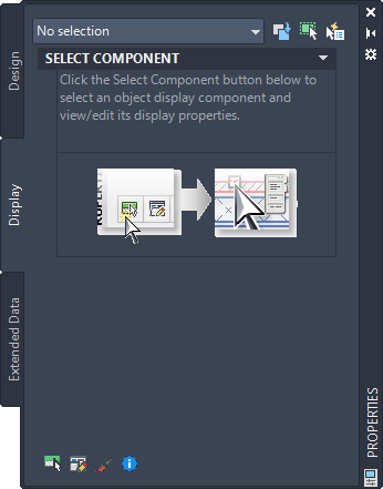
Display tab with no object selected
- Select an object in the drawing area. Note that the current display representation is identified under the General category on the Display tab

Display tab with one object selected
- Under the General category, for Display controlled by, select the level at which you want your changes applied.
If the value of Display controlled by is … Then your changes will apply to … Drawing default setting all objects of the same type for which no overrides are in effect (for example, all doors in the drawing). <object type>Style:<style name> (for example: Door Style: Hinged - Single) all objects with the specified style for which no object overrides are in effect. This is called a style override; it takes precedence over the drawing default setting. This object the selected object only. This is called an object override; it takes precedence over either the drawing default setting or the style. - Do one of the following:
If you want to … Then … change one or more display property settings for a particular object display component (or change the visibility setting for multiple components) proceed to step 6. view or modify display properties that apply to the entire object at the level currently specified by the value of Display controlled by for Display component, select *NONE*, then under the Object Display Properties category, change the value or click the worksheet button  for whichever property or set of properties you want to modify. The properties shown under this category depend on the type of object selected. For detailed information about modifying display properties for a specific object type, see the relevant Help topic, such as Walls or Doors. Each of these object topics contains subtopics for each category of display property.
 - To change one or more display property settings for a particular object display component, first use one of the following methods to select it:
- If an object is already selected, under the General category on the Display tab, select a component from the Display component drop-down list.
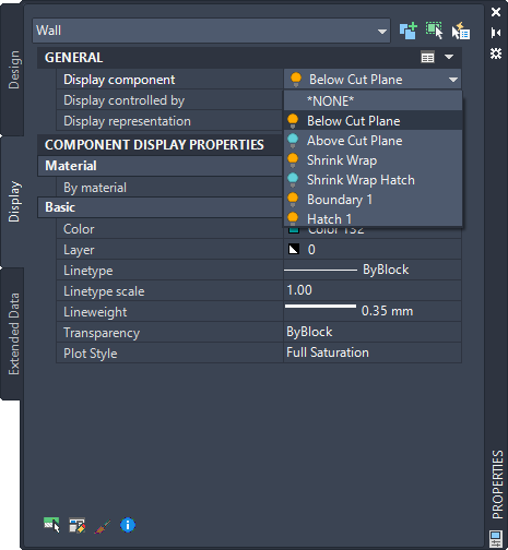
The color of the light bulb icon preceding each component name indicates whether the component is visible (yellow) or not (blue) in the current display representation. When the list is open, you can click one or more of these icons to change the visibility setting for the associated component(s). Your changes take effect in the drawing when you close the drop-down list by clicking a component name, pressing Enter, or clicking anywhere outside the list. Pressing Esc closes the list and cancels any visibility setting changes you have made while the list was open.
Tip: A hatch may obscure other components, which can be selected inadvertently when you click on the hatch in the drawing area.Therefore, the drop-down list is the preferred method for selecting solid hatch components. Note also that the drop-down list contains only components whose appearance is controlled by the display system. Clicking in the drawing area may result in the selection of an object or component whose display cannot be modified through the Display tab (such as MV blocks, custom blocks, AutoCAD objects, and other entities). In such cases, an error message will identify why the selection is invalid. - If no object is selected, at the bottom of the Display tab, click
 , and then click the display component in the drawing area.
 - Regardless of whether an object is selected, you can right-click in the drawing area, click Select Component, and then click the display component you want to modify.
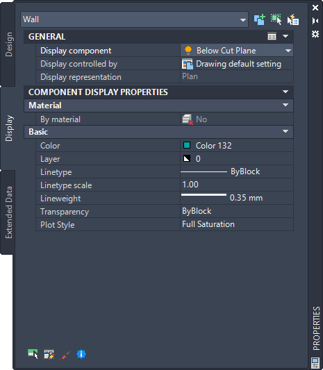
Display tab with object display component selected
Note: The property settings shown on the Display tab for a selected component are specific to the display system. In most cases these settings will not be the same as the settings (either default or override) for associated layers in the Layer Properties Manager. - If an object is already selected, under the General category on the Display tab, select a component from the Display component drop-down list.
- Enter or select a new value for any display properties you want to change. The results of your changes are immediately visible in the drawing area. Note that the properties shown on the Display tab vary depending on the object and component selected. Most are self-explanatory. For detailed information about modifying display properties for a specific object type, see the relevant Help topic, such as Walls or Doors. Each of these object topics contains subtopics for the applicable categories of display properties. Note: If the value of By Material is Yes, then your changes will apply to all objects with display components controlled by the material definition identified by the Name property, regardless of the value of Display controlled by. This is called a material definition override. When By material is Yes, you can access the drop-down list of material display components and change their visibility settings using the same technique described for display components in the previous step.In this case, the Display tab also includes an Advanced category under which the Additional Properties worksheet button
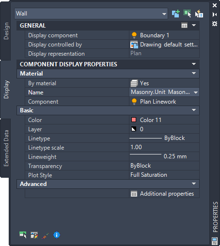
 accesses a dialog box where you can view and modify display properties associated with the material definition, such as surface hatch placement and surface rendering, as shown below.
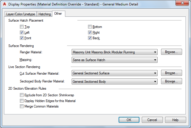
Other tab for material definition override
- If you want to apply your changes to other display representations at the same level indicated by the Display controlled by value, click the worksheet button
 on the title bar of the General category. (Note that the worksheet button is available only when a display component is selected, and the worksheet lists only those display representations that can be applied to that component.)
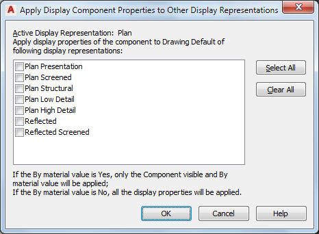
Worksheet for applying changes to other display representations
- On the worksheet, select the display representations to which you want your changes to apply, and click OK. Note: If the value of By material is Yes, only that setting and the Component visible setting will be applied to the selected display representations. If the value of By material is No, all of the display property settings for the component will be applied to the selected display representations.