Use this procedure to specify the properties of one or more cut planes for a door/window assembly style. Cut plane display properties apply only to display representations, such as Plan, that are used in Top view (Plan view) of a drawing.
To better visualize the elements of a door/window assembly in plan view, you can create cut planes. The main cut plane is where the shrinkwrap and hatching are applied. The plan display shows the components of the door/window assembly as they are displayed at the height of each cut plane.
- Click
 .
. 
- Expand Architectural Objects Door/Window Assembly Styles. Note: Alternatively, select a door/window assembly in the drawing, and click .

- Select the door/window assembly style that you want to change.
- Click the Display Properties tab.
- Select Plan, and click
 . Note: The Cut Plane tab is displayed only in some display representations, such as Plan.
 - Click the Cut Plane tab to set the cut plane to be displayed in each display representation for the door/window assembly style.
- Enter a value for Cut Plane Height to specify the cut plane at which hatching takes effect.
- To specifically define a cut plane, click Add, and enter the height of the new cut plane:
If you add a cut plane… Then… at a height that is lower than the value for Cut Plane Height objects are displayed using the properties specified for the Below Cut Plane component on the Layer/Color/Linetype tab. at a height that is higher than the value for Cut Plane Height objects are displayed using the properties specified for the Above Cut Plane component on the Layer/Color/Linetype tab. 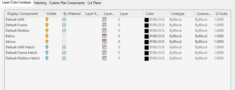
- Click OK twice.