Use this procedure to create a Drape mass element. A drape is useful when you are working with a conceptual model of a building site. You can create polylines and AEC Polygons at different elevations to represent topographic lines, and then drape a mass element over the polylines to show the contours of the site.
For the generated terrain surface, you can choose between a regular mesh with user-defined mesh density and mass element size, and a non-regular mesh defined by the input contour curves and points (Delaunay triangulation).
For a non-regular mesh, you can select either a rectangular mesh of user-specified size (the topography will be extrapolated from your input if the selected rectangular region is larger than the area covered by the contour curves and points), or a non-rectangular mesh whose surface size and shape are determined by the area of the input contour curves and points.
Creating a Drape mass element
- On the Massing tool palette, select the Drape tool.
Alternatively, you can click
 .
. 
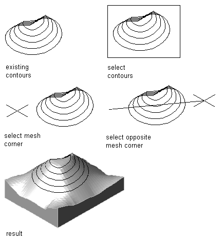
- Select the polylines or AEC Polygons to represent contours, and press Enter.
- Specify whether the source contours should be deleted after creating the drape mass element, and press Enter.
- Specify which mesh type you want to generate.
If you want… Then… a surface with user-defined mesh density and mass element size (non-triangulated surface) enter y (Yes) for Generate Regular Mesh [Yes/No]. a surface defined from the input contours and points (Delaunay triangulation) enter n (No) for Generate Regular Mesh [Yes/No]. - If you are generating a regular mesh, complete the following steps:
- Specify the first corner point of the mesh.
- Specify the opposite corner point of the mesh.
- Specify the mesh subdivisions in the X-direction.
- Specify the mesh subdivisions in the Y-direction.
- Enter the base thickness of the resulting mass element.
- If you are generating a non-regular mesh, specify whether you want it to be rectangular or non-rectangular:
If you want… Then… a rectangular mesh enter y (Yes) for Generate Rectangular Mesh [Yes/No]. a non-rectangular mesh enter n (No) for Generate Rectangular Mesh [Yes/No]. - If you are generating a non-regular, rectangular mesh, complete the following steps:
- Specify the first corner point of the mesh.
- Specify the opposite corner point of the mesh.
- Enter the base thickness of the resulting mass element.
Note: If the selected mesh area extends beyond the selected contours, the topography of the resulting mass element is extrapolated from the input values. - If you are generating a non-regular, non-rectangular mesh, enter the base thickness for the resulting mass element, and press Enter.