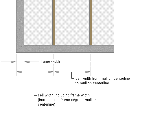
By default, grids cells are measured from the start and end points of the door/window assembly baseline (for horizontal divisions) or in the baseline to the base height (for vertical divisions). The width of the grid frame is not considered in calculating the size of the cell. For example, if you draw a door/window assembly with a 14 ft. baseline and a 1 ft. frame on the left and right, and you specify a fixed number of vertical cells, the cells do not appear equal in size. The first and last cells appear smaller because they include the frame.
To make the cells equal in size, offset the start and end of the grid by the width of the frame.
- Click
 .
. 
- Expand Architectural Objects Door/Window Assembly Styles. Note: Alternatively, select a door/window assembly in the drawing, and click .

- Select a door/window assembly style.
- Click the Design Rules tab.
- In the left pane, select Divisions under Element Definitions.
- Select a Divisions definition or click
 to create a new one.
 - Specify an offset for the grid.
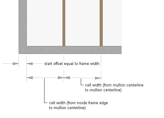
If you want to specify the distance between… Then… the start point of the door/window assembly baseline and the start of the first cell in a horizontal grid enter a value for Start Offset. the end point of the door/window assembly baseline and the end of the last cell in a horizontal grid enter a value for End Offset. the baseline of the door/window assembly and the start of the bottom cell in a vertical grid enter a value for Bottom Offset. the base height of the door/window assembly and the end of the top cell in a vertical grid enter a value for Top Offset. - Click OK.