Use this procedure to place a callout that creates a 2D section in the current project view drawing.
Note: The 2D section style and the display set for the model space view containing the section are set in the callout tool.
- On the Quick Access toolbar, click .

- Click the Views tab.
- Select the view drawing in which you want to place the section callout, right-click, and click Open.
- On the Tool Palettes, click
 (Properties), and click Document.
 - Click the Callouts palette.
- Select a section callout tool.
Alternatively, you can click
 , and select one of the section tools.
 - In the drawing area, specify the first point of the section line.
- Continue to add points to the section line. When you have finished the shape of the section line, press Enter.
- Specify the direction of the section mark arrow.

- Under New Model Space View Name, enter a name for the new model space view containing the section.
- Verify that Generate Section/Elevation is selected.
- If you want to add a title mark to the new model space view, select Place Titlemark.
- Select the scale for the model space view.
- Click Current Drawing.
- In the drawing area, select the insertion point for the model space view.
Once the model space view has been placed, the field placeholders in the section callout change to a question mark. To resolve them, the model space view needs to be placed onto a sheet.
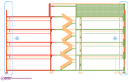
Building section view