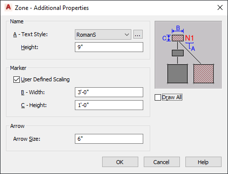
Use this procedure to specify the text style, zone marker size, and zone connection line arrow for a selected zone. You can also specify whether the zone hatch is used only for directly attached spaces of for those attached through subzones as well.
- Double-click the zone.
- On the Properties palette, click the Display tab.
- Under the General category, for Display component, verify that *NONE* is selected.
- For Display controlled by, select This object. Note: To apply your changes to all zones in the drawing, select Drawing default setting. To apply changes to all zones of this style, select Zone Style:<style name>.
- For Display representation, verify that the desired display representation is selected.
- If necessary, expand Object Display Properties
 Advanced.
 - Click
 Additional properties.
- Under Name, for Text Style, select a style for the zone name from the drop-down list, or click the worksheet button, and create a new text style, which will then be selectable from the list.
- For Height, enter the desired value.
- Under Marker, specify whether you want to define the scaling for the zone marker:
If you want to display the marker at… Then… 1/50 of the screen size clear User Defined Scaling. the scale you specify select User Defined Scaling, and enter the desired values for Width and Height. - Under Arrow, enter the desired value for Arrow Size.
- Specify which spaces will inherit the hatch of the zone:
If you want to… Then… use the zone hatch only for directly attached spaces clear Draw All. use the zone hatch for all directly attached spaces and all spaces attached through another zone select Draw All. - Click OK.