Controls many of the settings in the plotter configuration (PC3) file.
PLOTTERMANAGER (Command) Find:
Click the icon for any of the nodes to view and change its settings.
When you change a setting, your changes appear in angle brackets (< >) next to the setting name. A check mark is also displayed over the icon of the node with a changed value.
List of Options
The following options are displayed.
Media Node
Specifies a paper source, size, type, and destination. Available settings depend on the supported features of your configured plotter. For Windows system printers, you must configure the media settings using the Custom Properties node.
- Source and Size
-
Specifies the paper source and size.
- Source: Specifies the paper source; for example, sheet-fed or roll-fed. If you specify a tray, you can select the type of tray.
- Width: Specifies the width of the paper roll for a roll-fed source.
- Automatic: Enables the printer to specify the appropriate paper source.
- Size: Displays a list of available paper sources and both standard and custom paper sizes.
- Printable Bounds: Displays the print boundaries.
- Media Type
-
Displays a list of the media types supported by the plotter configuration.
- Duplex Printing
-
Determines double-sided printing and binding margin. Binding margin options are available only for plotters that support duplex printing.
- None: Indicates no double-sided printing.
- Short Side: Places the binding margin on the short side of the paper.
- Long Side: Places the binding margin on the long side of the paper.
- Media Destination
-
Displays a list of available media destinations for the configured plotter, such as collating, cutting, and stapling. These options are available only for plotters that support this function.
Physical Pen Configuration Node (for Pen Plotters Only)
Controls the specific pens in the pen plotter. The lower pane of the Device and Document Settings tab displays a table used to describe the color, width, and speed of each pen in the plotter.
- Pen Configuration
-
Specifies settings for pen plotters.
- Prompt for Pen Swapping: Use more than one pen while plotting on a single-pen plotter. Under Physical Pen Characteristics, you can specify settings for as many pens as you want. You are prompted when you need to change pens.
- Area Fill Correction: Enables the program to compensate for pen widths when plotting filled areas and wide polylines. Each polygon is shrunk by half of the width of the pen used to draw it. This option prevents the plotter from oversizing the filled area when using a wide pen and ensures precision. Use this option if the plot must be accurate to half the pen width, such as in printed circuit artwork.
- Pen Optimization Level: Reduces plot time and increases the efficiency of the pens by optimizing the pen motion. For example, you can prevent pens from retracing duplicate lines. If your drawing uses many colors or widths, you can reduce the time needed to change pens by selecting Adds Pen Sorting. Every object that uses a particular pen will be plotted before switching to another pen. Each method in the list includes the optimization methods preceding it in the list (except for No Optimization).
- Physical Pen Characteristics
-
To plot your drawing correctly on a pen plotter, you need to provide information about the pens in your plotter. For each pen in your plotter, specify a color and width. To optimize pen performance, you can specify a speed.
Note: This information is required; the physical pen information cannot be detected automatically.- Color: Specifies the colors of the pens in your plotter. The pen color that closely matches the object's color is selected. You can assign colors to your pens that correspond to each object's color. Use the Color list to select one of the following settings: No Pen, Red, Yellow, Green, Cyan, Blue, Magenta, Black, or Other. If you choose Other, the Select Color dialog box is displayed, providing access to the full color palette. Use No Pen to indicate that there is no pen in a particular position.
- Speed: Adjusts pen speed on a pen-by-pen basis. This feature is useful, for example, for slowing down pens that are skipping. Each pen manufacturer recommends a pen speed for each type of media. For best results, use those values. You can specify a pen speed in millimeters or inches per second.
- Width: Specifies the width of your pens so the program can determine if multiple pen strokes are needed to draw wide lines. You can specify the pen width in inches or millimeters. Be sure to select the pen width to match the actual width of the pen. The list provides a set of common pen widths.
Graphics Node
Specifies settings for printing vector graphics, raster graphics, and TrueType text. Depending on the capabilities of the plotter, you can modify color depth, resolution, and dithering. You can select either color or monochrome output for vector drawings. When printing raster images on a plotter with limited memory, you can improve performance by making some changes to the quality of the printed output. If you use a nonsystem plotter that supports varying amounts of installed RAM, you can provide that information to improve performance.
- Installed Memory
-
Provides the program with the amount of total memory (RAM) installed on a nonsystem plotter. This option is only available for non-Windows system printers that accept optional memory. If your plotter has extra memory, specify the total amount of memory.
- Total Installed Memory: Specifies the total installed memory in megabytes. The plotter driver uses the memory information to determine whether banding or image quality degradation is required to prevent the system from running out of memory.
- Vector Graphics
-
Provides options for specifying the color depth, resolution, and dithering of vector output. Some of the Vector Graphics options are closely interrelated; changing an option can affect other available options.
- Color Depth: Displays a list for choosing color depth for the configured plotter. The color depth options change as you change the resolution and dithering values. More color depth uses more memory and takes longer to plot. You can specify either color or monochrome output.
- Resolution: Adjusts the DPI (dots per inch) resolution of the configured plotter. Changing the DPI resolution changes the options available in the Dithering list. A higher resolution setting uses more memory and takes longer to plot than a lower resolution setting.
- Dithering: Specifies a dithering choice for non-pen-based plotters. Some dithering choices cause slower plotting.
- Raster Graphics (Non-Pen Plotters Only)
-
Specifies trade-offs between plotting speed and output quality when plotting raster objects on raster devices. If you reduce the image quality, you increase output speed. If your system resources are limited, reducing image quality can reduce the chance of running out of memory while plotting.
- Raster and Shaded/Rendered Viewports: Specifies a position on the slider that balances output quality with memory and plotting speed when plotting raster images and shaded viewports (rendered viewport plotting is not available in AutoCAD LT). Position the slider at None to disable raster image printing. Degrading the image quality lets you plot in less time. Position the slider at Best for the best output at the expense of memory and plotting speed.
- OLE: Specifies a position on the slider that balances output quality with memory use and plotting speed when plotting OLE objects. Position the slider at None to disable OLE object printing. Degrading the image quality lets you plot in less time. Position the slider at Best for the best output at the expense of memory and plotting speed.
- Trade-off: Specifies where to compromise quality if you can't output at the highest quality. Move the slider to diminish resolution and color.
- TrueType Text
-
On Windows system printers, specifies whether to plot TrueType text as a graphic image or as text.
Plotting as a graphic guarantees that the text is printed as displayed, at the expense of slowing down the plotter and using more memory. Plotting as TrueType text prints faster and uses less memory; the plotter may use a different font for printing.
- TrueType as Text: Plots TrueType text as text.
- TrueType as Graphics: Plots TrueType text as graphics.
- Merge Control
-
On raster plotters, controls the appearance of lines that cross. Merge control is not effective if your plotter is configured to plot everything as black or if you are using PostScript language.
- Lines Overwrite: Uses the last plotted line to obscure the lines under it. Only the topmost line is visible at the intersection.
- Lines Merge: Merges the colors of crossing lines.
Note: Merge control may appear as an option for system printers that do not actually support the feature. Please check your printer's documentation to determine if merge control is supported.
Custom Properties Node
-
Modifies the device-specific properties for the plotter configuration. The settings for each plotter vary. If the plotter manufacturer has not included a Custom Properties dialog box for the device driver, the Custom Properties option is not available.
For some drivers, such as ePlot, this is the only tree view option that is displayed. For Windows system printers, most of the device-specific settings are made in this dialog box. For more information about the custom properties settings for your device, choose Help in the Custom Properties dialog box.
Initialization Strings Node (for Non-System Plotters Only)
Sets pre-initialization, post-initialization, and termination ASCII text plotter strings, which send commands to a plotting device before and after the program initializes the device and after plotting is complete.
If you are plotting to an unsupported plotter in emulation mode, you can specify ASCII text initialization strings that prepare the plotter for printing, set device-specific options, and restore the plotter to its original state. You can also use initialization strings to turn on or off a plotting device feature that is not supported by the program.
The text string is sent literally, except for a back slash (). Use a back slash followed by a three-digit number (taken from the ASCII table), for example, 027, to specify binary (unprintable) characters such as the escape character. 027 is interpreted and sent as a single character whose value is 27. The number 27 is the escape character. For example, 27%-12345X PJL ENTER LANGUAGE = PostScript10 sends an HP PJL command to a dual-language laser printer before it's initialized and switches the printer into PostScript mode. The 027 sends an escape character and the 010 sends a line feed character. The remainder of the text string is sent literally. It is best to use three decimal digits for binary characters, so you'll need to add leading zeros as necessary.
Initialization strings should be used by advanced users only.
- Pre-Initialization
-
Forces a plotter to emulate another plotter by sending a pre-initialization ASCII text string to the plotter before it is initialized.
Use a back slash followed by a three-digit number (taken from the ASCII table), for example, 027, to specify binary (unprintable) characters such as the escape character.
- Post-Initialization
-
Sets a device-specific option that is not supported elsewhere in the program. Specify a post-initialization ASCII text string that is sent to the plotter after it is initialized.
Use a back slash followed by a three-digit number (taken from the ASCII table), for example, 027, to specify binary (unprintable) characters such as the escape character.
- Termination
-
Restores the printer to its original state after plotting. Specify a termination ASCII text string that is sent to the plotter after plotting is complete.
Use a back slash followed by a three-digit number (taken from the ASCII table), for example, 027, to specify binary (unprintable) characters such as the escape character.
User-Defined Paper Sizes & Calibration Node
Attaches a PMP file to the PC3 file, calibrates the plotter, and adds, deletes, revises, or filters custom paper sizes. You can also modify standard paper sizes. This node accesses the Plotter Calibration and Custom Paper Size wizards. If the plotter you are using has been calibrated, a Plotter Model Parameter (PMP) file contains that calibration information. If the PMP file is not already attached to the PC3 file you are editing, you must create that association so you can use the PMP file. If the plotter was calibrated from within the Add-a-Plotter wizard while creating the current PC3 file, the PMP file is already attached. Use the PMP File Name option under User-defined Paper Sizes & Calibration to attach a PMP file to, or detach the PMP file from, the PC3 file you are editing.
- Custom Paper Sizes (Nonsystem Printers Only)
-
Creates a customized paper size or changes the printable area of a standard or nonstandard paper size.
With the Custom Paper Size wizard you can create a new paper size, or select from a list of available paper sizes (from a PMP file) if the plotter is not a Windows system printer. If the plotter is a Windows system printer, use Custom Properties.
Each plotter has a maximum printable area determined by where it grips the paper and how far the pen shuttle can reach. If you are creating a paper size that is larger than the paper sizes offered in the Plotter Configuration Editor, verify that the plotter is capable of plotting the new dimensions.
- Add: Starts the Custom Paper Size wizard. When you add a paper size, you can either create a new paper size from scratch or create a new one based on the listing of available paper sizes for the selected configured plotter. The new paper size is a user-defined size, not a standard size.
- Delete: Deletes the selected custom paper size from the list.
- Edit: Starts the Custom Paper Size wizard, where you can modify the selected paper size. You can change any of the custom paper size settings.
- Modify Standard Paper Sizes
-
Adjusts the printable area for standard paper sizes to match the printer's capabilities. (You can't create custom paper sizes for Windows system printers using the Plotter Configuration Editor.)
- List of Standard Paper Sizes: Displays the available set of standard paper sizes.
- Modify: Starts the Custom Paper Size wizard. You can modify Printable Area and File Name. The new paper size is a user-defined size, not a standard size.
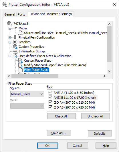
- Filter Paper Sizes
-
Filters the list of paper sizes displayed for the plotting device selected in the Plot and Page Setup dialog boxes. The list of paper sizes is displayed on the Plot Settings tab in the Plot dialog box and on the Layout Settings tab in the Page Setup dialog box.
Select the paper sizes you want to display for this device.
- Check All: Hides all the paper sizes for the device.
- Uncheck All: Displays all the paper sizes for the device.
- Plotter Calibration
-
Starts the Plotter Calibration wizard. If you need to correct scaling discrepancies, you can adjust the plotter calibration using the Plotter Calibration wizard. See “Calibrate Plotters and Work with Custom Paper Sizes” in the Driver and Peripheral Guide.
Note: You should perform a plotter calibration only if your drawings must be exactly to scale and your plotter or printer produces inaccurate plots. Plotter Calibration causes the program to rescale all plots sent to your plotter. If your plotter provides a calibration utility, it is recommended that you use it instead of the utility supplied with this program. - PMP File
-
Attaches a PMP file to or detaches a PMP file from the PC3 file you are editing. Use the Detach button to break the association between the PMP file and the PC3 file.
- Attach: Attaches a PMP file to the PC3 file. You can reuse calibration and custom paper size data stored in the PMP file.
- Save PMP: Saves a PMP file to a new file in the <product name>drv folder.
- Detach: Detaches the PMP file associated with the PC3 file you are editing.
Save As
-
Saves a PC3 File to a new file name.
Defaults
-
Restores the settings on the Device and Document Settings tab back to the default settings.