Bevels or chamfers the edges of two 2D objects or the adjacent faces of a 3D solid.
A bevel or chamfer is
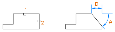
- an angled line that meets the endpoints of two straight 2D objects.
- a sloped transition between two surfaces or adjacent faces on a 3D solid.
The distances and angles that you specify are applied in the order that you select the objects.
Create 2D Chamfer
A bevel or chamfer can be defined by selecting two objects of the same or different object types: lines, polylines, rays, and xlines.
If the two selected objects are on the same layer, the line defined is created on that layer. Otherwise, the line is created on the current layer. The layer affects object properties including color and linetype.
The following prompts are displayed when creating a 2D chamfer.
First Line
Select the first of two objects or the first line segment of a 2D polyline to define the chamfer.
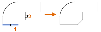
- Second line or shift-select to apply corner
-
Select the second object or line segment of a 2D polyline to define the chamfer.
You can also hold down the Shift key before selecting the second object or line segment of a 2D polyline to extend or trim the selected objects to form a sharp corner. While Shift is held down, a temporary value of zero is assigned to the current chamfer distance and angle values.
If the selected objects are straight line segments of a 2D polyline, the line segments can be adjacent to each other or separated by one other segment. When the selected segments are separated by a segment, the segment that separates them is removed and replaced with the chamfer.
Note: Adding a chamfer or bevel to a hatch boundary that was defined with individual objects results in the removal of hatch associativity. If the hatch boundary was defined from a polyline, associativity is maintained.
Undo
Reverses the previous action in the command.
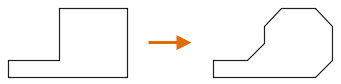
Polyline
Inserts a chamfer line at each vertex of a 2D polyline where two straight line segments meet. The chamfer lines become new segments of the polyline, unless the Trim option is set to No Trim.
Distance
Sets the chamfer distances from the intersecting points of the first and second objects.
If both distances are set to zero, the selected objects or line segments are extended or trimmed so they intersect.
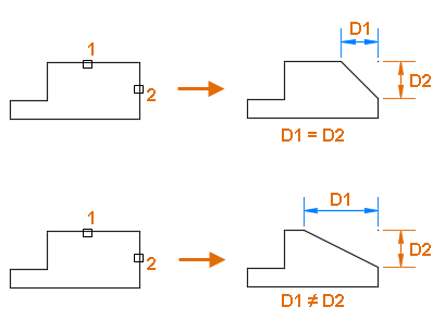
Angle
Sets the chamfer distance from the intersecting point of the selected objects and the XY angle from the first object or line segment.
If both values are set to zero, the selected objects or line segments are extended or trimmed so they intersect.
Trim
Controls whether the selected objects are trimmed to meet the endpoints of the chamfer line.
- Trim. Selected objects or line segments are trimmed to meet the endpoints of the chamfer line. If the selected objects or line segments do not intersect with the chamfer line, they are extended or trimmed before the chamfer line is added.
- No Trim. Selected objects or line segments are not trimmed before the chamfer line is added.
Method
Controls how the chamfer line is calculated from the intersecting point of the selected objects or line segments.
- Distance. Chamfer line is defined by two distances.
- Angle. Chamfer line is defined by a distance and an angle.
The current value is stored in the CHAMMODE system variable.
Multiple
Allows for the beveling of more than one set of objects.
Create 3D Chamfer (Not available in AutoCAD LT)
A chamfer can be added along the edge of a 3D solid or surface. When prompted to select the first line to define a chamfer, select the edge of a 3D solid or surface.
The following prompts are displayed after selecting the edge of a 3D solid or surface.
Enter Surface Selection Option
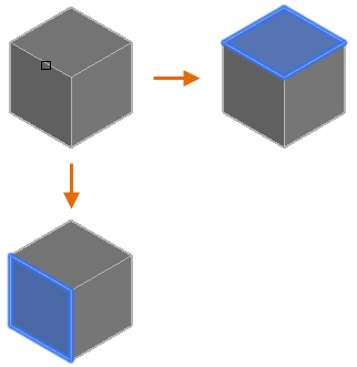
After the edge of a 3D solid or surface is selected, you can indicate which adjacent surface is the base surface. The base surface is the surface that defines which edges can be chamfered.
- Next. Selects the adjacent surface and sets it as the base surface.
- OK (Current). Accepts the selected surface as the base surface.
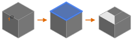
Once the base surface is selected, you specify the two chamfer distances and the edges of the base surface to chamfer.
Chamfer Distance
Sets the chamfer distances for the base and other (adjacent) surface.
Expression
Controls the chamfer distance with a mathematical expression.
See About Controlling Geometry With the Parameters Manager for a list of operators and functions allowed.
Edge
Select the edges of the base surface to chamfer. Press Enter to end selection.
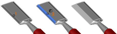
- Loop
-
Enables sequential tangent edge selection mode and allows for the selection of all edges that belong to the base surface.
For example, if the side of a 3D solid box is selected as the base surface, all tangential edges that belong to the side of the box are selected.
Use the Edge option to return to selecting individual edges that belong to the base surface.