After you add wire numbers to your schematics, annotate panel footprint symbols with this information. You can build panel footprint symbols with target attributes used for the wire connection information. If these attributes are not present on the panel footprint, a new or updated MTEXT entity displays the wire information.

Target Attributes
If the panel footprint blocks carry certain target attributes, they are used for the wire information. Each wire connection attribute definition is tied to a terminal attribute definition (TERMxx) by the matching two digit suffix on each attribute tag pair. The default value of the TERMxx attribute is used to match up the wire connection information from the schematic components.
- TERMxx - incremented for each wire connection. Carries the default pin value for the wire connection. The two digit suffix relates the attribute to the wire annotation attributes, WIRENOxx, WDEVxx, and WLEVxx.
- WIRENOxx - wire connection information is written to this attribute. Optionally, use WIRENOxxA, WIRENOxxB, and so on, to separate multiple wire connections across multiple attributes.
- WDEVxx - if present, the connected component part of the annotation is broken out and placed on this attribute.
- WLAYxx - if present, the connected wire layer part of the annotation is broken out and placed on this attribute.
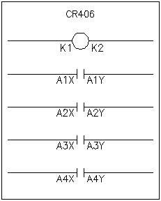
For example, here is a footprint representation for a 4-pole relay.

The TERMxx attribute definition default values match the default pin values for the relay, for example:
- Parent coil - K1, K2
- Child contact pairs - A1X/A1Y, A2X/ A2Y, A3X/A3Y, A4X/A4Y

When the wire connection information is added to the footprint, the match is made based on the TERMxx value match.
MText
The default MText insertion point is the same as the insertion point of the footprint block. The default text size either matches that of existing wire number attributes found on the footprint symbol or, if none present, the MText size is forced to match the current value of the AutoCAD system variable "TEXTSIZE".
To predefine the MText insertion point, text size, and text style on footprint blocks, insert an invisible attribute "WXREF" on your footprint block library symbol. Open up each footprint symbol in AutoCAD and insert a blank attribute definition "WXREF". Put its origin at the point where you want AutoCAD Electrical toolset to insert the MText wire connection information. Mark this attribute definition invisible and set its text size and style to the desired MText size and style.