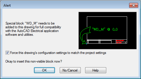
A special invisible block must be present on the drawing. The WD_M.dwg is found in the default symbol library. Here is an attribute list of information that is carried on the WD_M block of the drawing, sorted by category:

Drawing layout
|
SHEET or SHEET_ |
sheet number for the drawing (%S) |
|
SHEETDWGNAME |
optional drawing number for the drawing (%D) |
|
IEC_PROJ |
optional IEC project code (%P) |
|
IEC_INST |
optional IEC installation code (%I) |
|
IEC_LOC |
optional IEC location code (%L) |
|
UNIT_SCL |
units scaling factor (1.0 = inch, 1.0 = full-size mm, 25.4 = inch scaled up to mm) |
|
FEATURE_SCL |
scaling adjustment (0 = default, 1.25=for 25% bigger) |
Ladder defaults
|
RUNGHORV |
ladder orientation: "H" = horizontal rungs (vertical ladders); "V" = vertical rungs (horizontal ladders) |
|
REFNUMS |
reference numbering system: ladder line reference-based or X-Y grid reference-based
|
|
RUNGDIST |
default rung spacing |
|
DLADW |
default ladder width |
|
RUNGINC |
default rung-to-rung line reference increment (default = 1) |
|
DRWRUNG |
draw ladder rungs: 0 = none, 1 = draw all rungs for new ladder, 2 = skip 1, 3 = skip 2, and so on. |
|
PH3SPACE |
3-phase bus spacing value |
Component tagging
|
TAGMODE |
tag mode value: S = sequential, R = reference-based |
|
TAG-START |
starting sequential number of the drawing -for sequential tagging only (that is, "1") |
|
TAG-RSUF |
comma-delimited component tag suffix list -for reference-based tagging only (that is, "A, B, C") |
|
TAGFMT |
component tag format specifier (default=%F%N) |
Wire number tagging
|
WIREMODE |
wire number format: S = sequential, R = reference-based |
|
WIRE-START |
starting sequential number of the drawing - for sequential tagging only (that is, "100") |
|
WIRE-RSUF |
wire tag suffix list - for reference-based tagging only (that is, "A,B,C") |
|
WIREFMT |
wire tag format specifier (default=%N) |
|
WINC |
wire number increment |
|
WLEADERS |
wire leaders: 0 = only as required, 1 = always insert wire leaders, 2 = never insert leaders |
|
GAP_STYLE |
wire gap style: 0 = wire gap, 1 = use loops across gaps, 2 = solid crossing (no gap) |
|
SORTMODE |
retag and wire numbering sort mode |
|
WNUM_OFFSET |
wire number placement offset distance (GBL_wd_wnum_offset); same as the project-wide +[19] value in the .wdp file. 0.0 or missing= centered on wire (default), >0.0 = offset from top or left end by given distance |
|
WNUM_FLAGS |
|
Layer names
|
TAG_LAY |
component tag layer |
|
TAGFIXED_LAY |
fixed component tag layer |
|
DESC_LAY |
description layer of the parent component |
|
CDESC_LAY |
description layer of the child component |
|
TERM_LAY |
component terminal pin numbers layer |
|
XREF_LAY |
cross-reference layer of the parent component |
|
CXREF_LAY |
cross-reference layer of the child component |
|
LOC_LAY |
component location code layer |
|
POS_LAY |
component position code layer |
|
MISC_LAY |
miscellaneous layer |
|
COMP_LAY |
layer for schematic component graphics |
|
LINK_LAY |
dashed link lines layer |
|
LOCBOX_LAY |
location box layer |
|
WIRELAYS |
valid wire layer names where "" = all valid (comma-delimited) |
|
WIRENO_LAY |
valid wire number |
|
WIRECOPY_LAY |
extra wire number layer |
|
WIREFIXED_LAY |
fixed wire layer |
|
WIREREF_LAY |
terminal and signal arrow wire number layer |
Fan In/Out
|
FAN_INOUT_LAYS |
valid layer names for Fan In/Out, single-line wires (comma-delimited) |
|
FAN_INOUT_STYLE |
Fan In/Out symbol style number |
Cross-reference
|
XREFFMT |
cross-reference format specifier (default=%N) |
|
ALT_XREFFMT |
optional cross-reference format for inter-drawing references (that is, %S-%N) |
|
XREF_STYLE |
cross-reference style: 0 = text, 1 = graphical, 2 = table |
|
XREF_FLAGS |
1's bit = include unused contacts, 2's bit (if table)= include parent coil |
|
XREF_UNUSEDSTYLE |
0 = separate reference, 1 = contact count totals |
|
XREF_FILLWITH |
cross-reference fill-with text |
|
XREF_SORT |
0 = sort by line reference, 1 = sort by pin list |
|
XREF_TXTBTWN |
cross-reference text between references (text style cross-referencing) |
|
XREF_GRAPHIC |
0 = graphic, 1 = contact mapping (text), 2 = symbol mapping |
|
XREF_GRAPHICSTYLE |
0 = JIC, 1 = IEC |
|
XREF_CONTACTMAP |
contact mapping list |
|
XREF_TBLSTYLE |
table style name |
|
XREF_TBLTITLE |
table title |
|
XREF_TBLINDEX |
table fields to include |
|
XREF_TBLFLDNAMS |
table available field names |
|
XREF_TBLCOLJUST |
table fields justification |
Referencing
|
DATUMX |
X coordinate origin for X-Y or X-zone |
|
DATUMY |
Y coordinate origin for X-Y or X-zone |
|
DISTH |
horizontal interval spacing for X-Y or X-zone |
|
DISTV |
vertical interval spacing for X-Y referencing |
|
CHAR_H |
horizontal starting character for X-Y or X-zone |
|
CHAR_V |
vertical starting character for X-Y referencing |
|
HORIZ_FIRST |
X-Y referencing format: 0 = V-H, 1 = H-V |
|
XY_DELIM |
X-Y delimiter character |
Styles
|
PLC_STYLE |
PLC module style code (default = 1) |
|
ARROW_STYLE |
default signal arrow style number |
Miscellaneous
|
WNUM_GAP |
list of 3 in line wire number/label gap settings (see WNUM_FLAGS bit 1 for toggle mode); value saved to GBL_wd_inline_gap as a list. nil or "(num1 num2 num3)" |
|
MISC_FLAGS |
miscellaneous flags
|