Circuit Builder uses an electrical standards database to define default values, define engineering calculations, annotate circuits, and provide wire size recommendations. The electrical standards database, ace_electrical_standards.mdb, is located in the catalog folder. The default location is C:\Users\{username}\Documents\Acade {version}\AeData\Catalogs\.
Sizing and wire type values are based on information from the electrical standards database. Circuit Builder looks for a match on the motor size, supply voltage, and phase. On a match, Circuit Builder provides the Full Load Amp value, recommended motor power conductor size, and suggested rating values for various branch circuit protection elements such as circuit breakers, fuses, and disconnect switches.
The electrical standards database also allows Circuit Builder to provide engineering estimates and “green” calculations in the area of power conductor size versus energy losses. Designing to meet minimum code requirements can conflict with green design. For example, designing to the minimum conductor size for a given load can provide short-term savings on material cost but run up longer-term expense due to higher heating loses in the wiring. Over the life of the installation, the energy lost in heating up the minimum-sized wiring, instead of reaching the load to do useful work, could be substantial.
During wiring sizing, Circuit Builder displays not only a list of the valid wire sizes meeting the ampacity requirements of the load, but also a list of the estimated maximum energy loss cost for each wire size. This set of calculations allows you to make better green design decisions. For example, you decide to oversize the conductors for a motor to reduce conductor heating losses. This results in a higher initial cost for material and installation labor. However, this cost is recovered many times over in reduced energy losses in the wiring during the life of the installation.
The electrical standards database contains multiple tables used by Circuit Builder.
|
MOTOR |
Contains the values used to populate the Select Motor dialog box. |
|
FEED |
Contains the values used to populate the Select Load dialog box. This table name can have an optional suffix to relate it to a specific electrical standards code. |
|
OPT |
Options tables contain values defining defaults and options lists specific to an electrical standard. For example, default to copper wiring, AWG size standard, and feet for conductor length units. |
|
AMP_{wire type}_{wire size standard} |
Wire ampacity tables contain the ampacity ratings for different conductor sizes and insulation temperature ratings. |
|
AMPG_{wire type}_{wire size standard} |
Grounding conductor sizing tables contain the maximum ampacity ratings for different grounding conductor sizes. This information is used to retrieve the minimum grounding conductor size and provide a selection list of larger sizes. |
|
INSUL_{wire type}_{wire size standard} |
Wire insulation tables lists the insulation types, the maximum temperature rating for each, and de-rating factors for each based on a series of temperatures. |
|
XL&R_{wire type}_{wire size standard} |
Conductor Reactance/AC Resistance tables contain values used to estimate single-phase and three-phase voltage drop values. |
|
XL&R_DESC |
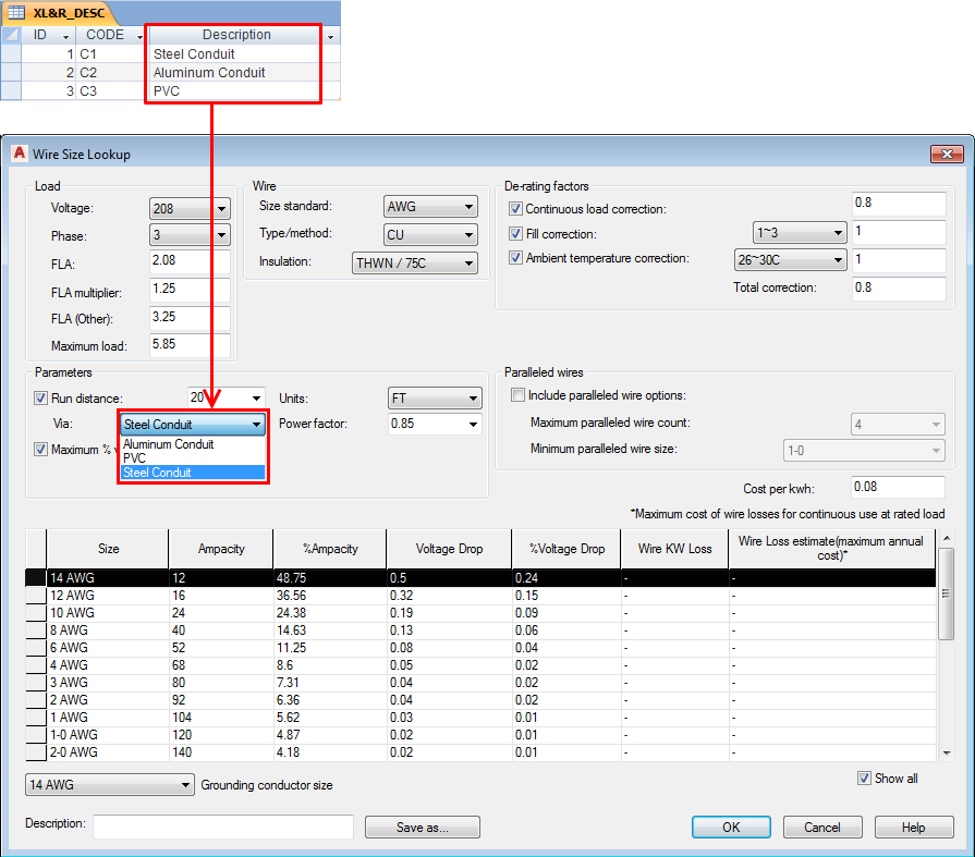
Conduit/raceway descriptions list used with the XL&R_{wire type}_{wire size standard} tables. |
|
FILL |
Fill tables contain the ampacity de-rating factors used when there is more than one current carrying conductor (power wiring, not ground, neutral, or control wires) in the same conduit, duct, or raceway. |
|
MOTOR_I_DESC |
Lists the component type descriptions whose sizing ties directly into the full load amps value (FLA) of the motor or load. The CODE value maps to the MOTOR_I_CALC and MOTOR_I_MAP tables. |
|
MOTOR_I_CALC |
Lists the formula to calculate the maximum amp value for various types of components on a per motor type basis. |
|
MOTOR_I_MAP |
Maps the calculated FLA for a component to a specific rating value and an optional catalog assignment. |
Each table name can have an optional suffix to relate it to a specific electrical standards code. Circuit Builder searches for a table using the following sequence:
- Tables with the three character Electrical code standard suffix.
- Tables without a suffix.
- Tables with an “NEC” suffix.
Motor table
The data in the Motor table is used to populate the Select Motor dialog box. Filter the selection list by type, voltage, and frequency. The load and FLA values for the selected motor are passed back to the Circuit Configuration dialog box and are used in wire size calculations. The values are also used to calculate breaker size, fuse size, and disconnect switch rating, for the selected motor.
The MOTOR table follows this table naming convention:
- MOTOR - if no specific electrical standards table is found, the default table name to use.
- _{standard} - optional suffix to relate it to a specific electrical standards code. For example, an “_NEC” suffix could mean that the data for the table parallels the National Electrical Code. A suffixed MOTOR table name is not necessary unless you plan to set up the electrical standards database to support multiple standards.
Feed table
The data in the Feed table is used to populate the Select Load dialog box. Filter the selection list by type, voltage, and frequency. The load and FLA values for the selected feed are passed back to the Circuit Configuration dialog box and are used in wire size calculations. The values are also used to calculate breaker size, fuse size, and disconnect switch rating, for the selected load.
The FEED table follows this table naming convention:
- FEED - if no specific electrical standards table is found, the default table name to use.
- _{standard} - optional suffix to relate it to a specific electrical standards code. For example, an “_NEC” suffix could mean that the data for the table parallels the National Electrical Code. A suffixed FEED table name is not necessary unless you plan to set up the electrical standards database to support multiple standards.
Options tables
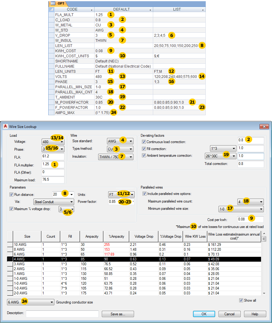
Options tables contain values defining defaults and options lists specific to an electrical standard. For example, default to copper wiring, AWG size standard, and feet for conductor length units.
The OPT table follows this table naming convention:
- OPT - if no specific electrical standards table is found, the default table name to use.
- _{standard} - optional suffix to relate it to a specific electrical standards code. For example, an “_NEC” suffix could mean that the data for the table parallels the National Electrical Code. A suffixed OPT table name is not necessary unless you plan to set up the electrical standards database to support multiple standards.
|
Name |
Description |
|---|---|
|
FLA_MULT |
Default full load amps multiplier value used to determine a maximum load. For example, the full load amps for a motor is rated at 10 amps and the FLA_MULT default is set to 1.25. The minimum wire size calculation for the wiring for the motor is based upon an ampacity rating of not 10 amps but 12.5 amps (10 amps x 1.25). The FLA_MULT factor displays in the Select Motor and Wire Size Lookup dialog boxes. |
|
C_LOAD |
Continuous load correction factor for wire size ampacity de-rating. If the electrical load is anticipated to be a continuous load, a default de-rating factor can be automatically applied to the wire size ampacity calculation. For example, a given electrical code defines the Continuous load correction factor at a value of 0.8. This means that a given wire size that normally has a maximum rated ampacity value of 20 amps is de-rated to a maximum ampacity of 16 amps when the wiring is to power a motor that is expected to be a continuous load. The wire size calculation may need to select the next larger wire size. |
|
W_METAL |
Default wire metal value used to determine appropriate wire ampacity and wire insulation table names. For example, “CU” to define copper wiring as the default, “AL” to define aluminum wiring as the default. |
|
W_STD |
Default wire type standard used to determine appropriate wire ampacity and wire insulation table names. For example, “AWG” or “MM2”. |
|
V_DROP |
Maximum allowable % voltage drop in power wiring. This value can be used to help calculate an appropriate wire size when the wire run distance is also defined. |
|
W_INSUL |
Default insulation type used to determine the ambient temperature correction factor. |
|
LEN_LIST |
Wire run distance values for pick list in the Wire Size Lookup dialog box. The run distance is used for estimated voltage drop calculations in the motor or load power wiring. |
|
LEN_UNITS |
Run distance units for power conductors and values for units pick list in the Wire Size Lookup dialog box. Run distance is used in the estimated voltage drop calculation. Units are either "FT" for feet or "M" for meters. |
|
KWH_COST |
Unit cost per kWh. This value is used for estimating a maximum annual cost of energy loss in the power wiring for a motor or load, assuming a continuous full load. |
|
KWH_COST_UNITS |
KWh cost units character used in the Wire Size Lookup dialog box showing the wire loss estimates. For example, “$” for dollar, “€” for euro. |
|
SHORTNAME |
The code for the electrical standards name for this table. This code is saved in the project .wdp file when the standard is applied to a project. |
|
FULLNAME |
The full name of the electrical standards name for this table. This value, extracted from all the OPT tables, provides the values for the pick list when setting an Electrical Code Standard for a project from the Project properties: project settings tab. |
|
LEN_UNITS |
Run distance units for power conductors and values for units pick list in the Wire Size Lookup dialog box. Run distance is used in the voltage drop calculation. |
|
VOLTS |
Default supply voltage value and values for voltage pick list in the Wire Size Lookup dialog box. |
|
PHASE |
Default supply phase value and values for phase pick list in the Wire Size Lookup dialog box. For example, “1” for single-phase, “3” for three-phase. |
|
PARALLEL_MIN_SIZE |
Default value for the minimum wire size when displaying paralleled wire option in the Wire Size Lookup dialog box. For example, “1-0 AWG”. |
|
PARALLEL_MAX_CNT |
Default value for the maximum number of wire conductors when displaying paralleled wire option in the Wire Size Lookup dialog box. For example, “4” for up to four paralleled wires per phase. |
|
T_AMBIENT |
Default ambient temperature correction factor. This value is used in wire type sizing. It must match up with one of the temperature de-rating column labels found in the INSUL_* tables. For example, “30C”. |
|
M_POWERFACTOR |
Default power factor for a motor. This value is used in estimated voltage drop calculations. For example, “0.85”. |
|
F_POWERFACTOR |
Default power factor for a power feed. This value is used in estimated voltage drop calculations. For example, “0.85”. |
|
AMPG_MAX |
Defines the expression to calculate the minimum grounding conductor ampacity size. The “I” in the expression represents the motor or load full load amps (FLA). The result of the expression is then applied to the appropriate AMPG table to determine the minimum grounding conductor size. |

Wire ampacity tables
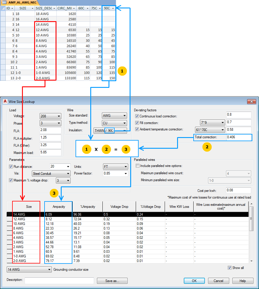
The wire ampacity tables provide the wire conductor sizes, descriptions, and maximum FLA ampacity values based on wire size and standard insulation temperature ratings. This information is used in the following ways:
- Automatically select a default wire size based upon the maximum load amp value displayed in the Select Motor or Select Load dialog boxes.
- Automatically calculate or recalculate suggested wire sizes in the Wire Size Lookup dialog box as various parameters and de-rating factors are applied.
The wire ampacity tables use the following naming convention:
- AMP - the table name prefix.
- _{type} - the wire metal type such as CU for copper, or AL for aluminum.
- _{size} - wire size standard such as AWG, or MM2 for metric.
- _{standard} - optional suffix to relate it to a specific electrical standards code. For example, an “_NEC” suffix could mean that the data for the table parallels the National Electrical Code. A suffixed table name is not necessary unless you plan to set up the electrical standards database to support multiple standards.
For example, a table named AMP_CU_AWG_NEC contains the wire ampacity information for copper, AWG sizes, and parallels what is found in the National Electrical Code.
|
Name |
Description |
|---|---|
|
SIZE |
Wire size code. This value can be automatically pushed into a wire type layer name. For example, “12”, “250KCMIL”. |
|
SIZE_DESC |
Wire size description shown on the Wire Size Lookup dialog box. For example, “12 AWG”, “250 KCMIL”. |
|
CIRC_MIL |
Imperial cross-section value for the wire conductor size. |
|
60C, 75C, 90C |
Maximum ampacity rating values for the wire conductor size for each of these standard ambient temperature ratings. Additional columns can be added or an existing column can be deleted. For example, if local electrical codes do not support 90C, this field can be removed from the table and does not show up as an option in the Wire Size Lookup dialog box. |

Grounding conductor sizing tables
The grounding conductor sizing tables provide the grounding wire conductor sizes and maximum FLA ampacity values. This information is used in the following ways:
- Provide a suggested minimum grounding conductor size based on the amp value returned by the expression defined in the AMPG_MAX entry in the OPT table.
- Provide a selection list on the Wire Size Lookup dialog box giving this minimum suggested size plus all larger grounding conductor sizes.
The grounding conductor sizing tables use the following naming convention:
- AMPG - the table name prefix
- _{type} - the wire metal type such as CU for copper, or AL for aluminum.
- _{size} - wire size standard such as AWG, or MM2 for metric.
- _{standard} - optional suffix to relate it to a specific electrical standards code. For example, an “_NEC” suffix could mean that the data for the table parallels the National Electrical Code. A suffixed table name is not necessary unless you plan to set up the electrical standards database to support multiple standards.
For example, a table named AMPG_CU_AWG_NEC contains the grounding conductor sizing information for copper, AWG sizes, and parallels values found in the National Electrical Code.
|
Name |
Description |
|---|---|
|
SIZE |
Wire size code. This value can be automatically pushed into a wire type layer name for the ground wire. For example, “12”, “250KCMIL”. |
|
SIZE_DESC |
Wire size description shown on the Wire Size Lookup dialog box. For example, “12 AWG”, “250 KCMIL”. |
|
MAX |
Maximum amp value associated to this grounding wire size. The value comes from the result of the expression held in the AMPG_MAX entry of the OPT table. |
Wire insulation tables
The wire insulation tables provide the option to de-rate wire conductor ampacity based upon expected maximum ambient temperature.
- Automatically select a default wire size based upon the maximum load amp value, displayed in the Select Motor or Select Load dialog boxes, and the default insulation type and ambient temperature rating defined in the W_INSUL and T_AMBIENT entries of the OPT table.
- Automatically calculate or recalculate suggested wire sizes in the Wire Size Lookup dialog box as various insulation and temperature de-rating factors are applied.
The wire insulation tables use the following naming convention:
- INSUL - the table name prefix.
- _{type} - the wire metal type such as CU for copper, or AL for aluminum.
- _{size} - wire size standard such as AWG, or MM2 for metric.
- _{standard} - optional suffix to relate it to a specific electrical standards code. For example, an “_NEC” suffix could mean that the data for the table parallels the National Electrical Code. A suffixed table name is not necessary unless you plan to set up the electrical standards database to support multiple standards.
For example, a table named INSUL_CU_AWG_NEC contains the wire insulation information for copper, AWG sizes, and parallels values found in the National Electrical Code.
|
Name |
Description |
|---|---|
|
INSUL |
Insulation type code. |
|
INSUL_DESC |
Insulation type description shown on the Wire Size Lookup dialog box. |
|
TEMP |
Standard, maximum temperature rating for the insulation type. |
|
25C-80C |
A series of wire conductor ampacity de-rating factor values for maximum ambient temperature. Columns can be added or deleted. For example, if 30C is the minimum ambient temperature rating, the 25C column can be removed. |

Conductor Reactance / AC Resistance tables
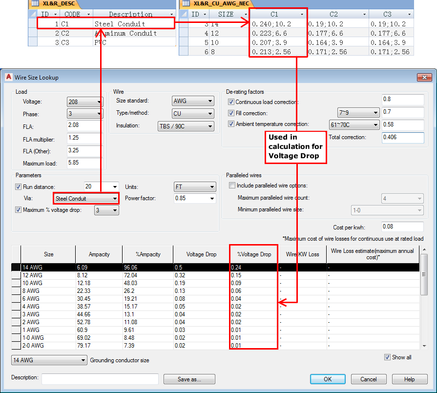
The optional conductor reactance/AC resistance tables provide the reactance and resistance values for wire size based on conduit type. These values are used to calculate the voltage drop percentage in power wiring when a run distance is supplied.
There are two types of tables for this feature. A conduit type description table and the reactance/resistance data tables.
Conduit type description table
The description table, XL&R_DESC, contains the labels used on the Wire Size Lookup dialog box for the conduit or raceway type selection list. The labels also map to the columns in the data tables.

Data tables
The conductor reactance/AC resistance data tables use the following naming convention:
- XL&R - the table name prefix
- _{type} - the wire metal type such as CU for copper, or AL for aluminum.
- _{size} - wire size standard such as AWG, or MM2 for metric.
- _{standard} - optional suffix to relate it to a specific electrical standards code. For example, an “_NEC” suffix could mean that the data for the table parallels the National Electrical Code. A suffixed table name is not necessary unless you plan to set up the electrical standards database to support multiple standards.
For example, a table named XL&R_CU_AWG_NEC contains the conductor reactance/AC resistance information for copper, AWG sizes, and parallels values found in the National Electrical Code.
|
Name |
Description |
|---|---|
|
SIZE |
Wire size code. |
|
C1-C3 |
A set of reactance and resistance values, semi-colon delimited for the conduit type. The first element is the estimated reactance and the second element is the AC resistance. Note:
see the XL&R_DESC table for the corresponding label for each. Data for additional conduit/raceway types can be added to this table with a corresponding entry added to the XL&R_DESC table. |

Fill tables
When multiple current carrying wire conductors are in the same conduit, duct, or raceway, the wire ampacity may need to be de-rated. Current carrying wire conductors are defined as power wiring, not ground, neutral, or control wires. The Fill table provides the de-rating factor based on the maximum number of power wire conductors.
The FILL table follows this naming convention:
- FILL - the table name prefix.
- _{standard} - optional suffix to relate it to a specific electrical standards code. For example, an “_NEC” suffix could mean that the data for the table parallels the National Electrical Code. A suffixed FILL table name is not necessary unless you plan to set up the electrical standards database to support multiple standards.

MOTOR_I* tables
A set of three tables containing values used for calculating suggested breaker size, fuse size, and disconnect switch ratings for a given motor or load amp value. Each table name can have an optional suffix to relate it to a specific electrical standards code such as “_NEC” for National Electrical Code.
MOTOR_I_DESC
Lists the component type descriptions whose sizing ties directly into the full load amps value (FLA) of the motor or load. The CODE value maps to the MOTOR_I_CALC and MOTOR_I_MAP tables.
MOTOR_I_CALC
Lists the formula to calculate the maximum amp value for various types of components on a per motor type basis. Each row gives a motor type followed by columns marked with the codes given in the MOTOR_I_DESC table. Each cell contains an expression to calculate a FLA value. The FLA value for the selected motor corresponds to the symbol "I" in the expression.
Valid operations are +-*/^. The “^” character is the exponential function. For example, I^2 is I squared, while I^0.5 is the square root of I.
If-then-else statements are supported including one level of nested statements. For example,
- (if (I > 400) then (I * 8) else (I * 11)) - the calculated amp value is eight times FLA current for 0-400 amps and 11 times for greater than FLA of 400 amps. One level of nesting is supported.
- (if (I >= 9.0) then (I * 1.25) else if (I < 2.0) then (I * 3.0) else (I * 1.67) - the calculated value is set to (I * 1.67) if I is less than 9 but greater or equal to 2.0 amps. If I is less than 2.0 amps the calculated value is (I * 3.0), and if greater than or equal to 9.0 amps, it is (I * 1.25).
Valid Boolean operations are >, <. >=. <=, =.
MOTOR_I_MAP
Maps the calculated FLA for a component to a specific rating value and an optional catalog assignment. The rating value is annotated to the symbol using the API call c:ace_cb_anno2 in the circuit builder spreadsheet.
The optional catalog assignment is defined in the Default field. Use the following format:
MFG={manufacturer};CAT={catalog};ASSYCODE={assembly code}
If the ASSYCODE value is not needed, use the format:
MFG={manufacturer};CAT={catalog}
CATALOGSEL table
Circuit Builder uses the CATALOGSEL table to save the catalog selections made for the motor and other components. The catalog information is saved based on the motor size. If this same motor size is used later on another circuit, these previous catalog selections become the default values when they match up with the configured selections. For example, if the previous circuit was configured with a 10HP motor with time-delay fuses, and a 10HP motor with time-delay fuses is selected for the new circuit, the previously used catalog selection appears as the default.
If the circuit is configured using the Reference an existing circuit feature, the values are not used from the CATALOGSEL table but from the referenced circuit. However, if a new motor is then selected from the Select Motor dialog box, the CATALOGSEL tables values are checked for a match.