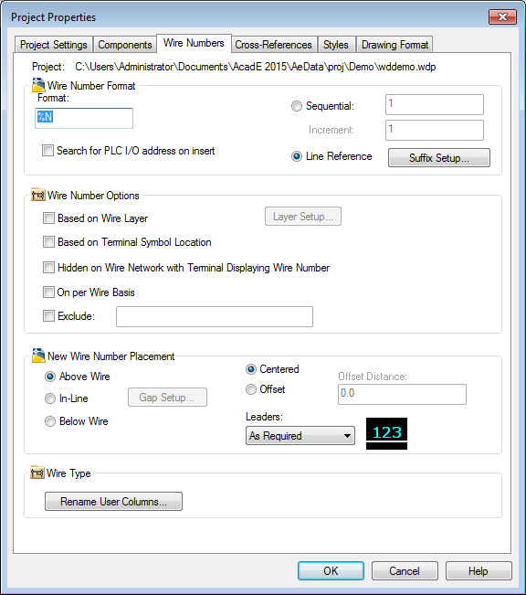
Use the Project Properties dialog box to define settings when creating a project. Then have the settings used for new drawings or the settings added to the project. In the Project Properties dialog box, icons indicate whether the settings apply to project settings or drawing defaults.
|
|
Properties that are saved in the project file as drawing defaults. These properties have corresponding drawing properties which control the functionality. |
|
|
Properties that are saved in the project file as project settings. These properties do not have corresponding drawing properties and control the functionality for the entire project. |

Use the Drawing Properties dialog box to define settings for a new or selected drawing. These settings override the project properties set in the Project Properties dialog box. If the drawing is part of a project, the project name displays in the dialog box. Otherwise, text displays indicating that the drawing is not part of a project, and drawing-related edit fields saved in the .wdp file are disabled.
You can specify settings for the project or drawing defaults, components, wire numbers, cross-references, styles, and the drawing format using either the Project Properties or Drawing Properties dialog boxes. An overview of the available options for each tab are listed in the following section.
Settings
Project settings include:
- Library and Icon Menu paths
- Catalog lookup file preferences
- Real-time error checking options
Drawing settings include:
- Drawing type and descriptions
- Default values for the Project (%P), Installation (%I), and Location (%L) fields
- Sheet values for the sheet and drawing in addition to section or subsection codes
Components
Use this tab to:
- Specify the way new component tags are created.
- Switch between sequential or line reference based tags.
- Set component tag options such as using combined Installation/Location tags or suppressing the Installation/Location tag on reports.
- Display description text in uppercase.
Wire Numbers
Use this tab to:
- Set the wire number format.
- Switch between sequential or line reference based wire numbers.
- Set wire number options such as hidden numbers, excluded numbers, or displaying numbers on a per wire basis.
- Set up wire number layer options.
- Define wire number placement: above, below, or in-line.
- Define wire number leaders.
Cross-references
Use this tab to:
- Define the cross-reference annotation format.
- Set cross-reference options such as suppressing Installation/Location codes or using real-time signal and contact cross-referencing between drawings.
- Set component cross-reference display: text, graphical, or table. You can also change the display format setup from this dialog box.
Styles
Use this tab to:
- Change default styles for arrows, plcs, fan-in/out markers, and wiring.
- Add or remove layers from the layer list.
Drawing Format
Use this tab to:
- Set the default orientation, spacing, and width values for any new ladders inserted on the drawing.
- Specify the format referencing style: X-Y Grid, X Zones, or Reference Numbers.
- Set the scale factor used when inserting new components or wire numbers on the drawing.
- Set the tag/wire number sort order.
- Define and manage wire and component layers.