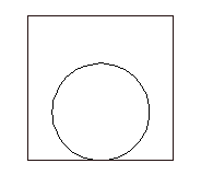
A panel footprint symbol can be in either of two general forms: a to-scale physical representation of the device or a generic wiring diagram representation whose main purpose is to show wire connection annotation information.
The procedure for creating a panel footprint is like that of creating a schematic symbol with the following differences:
- Panel footprint symbols do not have to carry the wire connection attributes that schematic symbols almost always carry.
- There are no parent/child versions of a symbol for panel footprint symbols.
- Some of the attribute names are different. A panel symbol must have the P_TAG1 or P_TAGSTRIP attribute rather than the TAG1 or TAGSTRIP attribute.
- The symbol block naming for the panel footprint does not follow the special naming convention. The first four or five characters of the block name for a panel symbol is not as critical as it is for schematic symbols.
In this example, you take geometry (either geometry you just drew, existing geometry, or a vendor representation) and convert it to an AutoCAD Electrical toolset panel footprint using the Symbol Builder.
- Click


 . Find
- In the Select Symbol/Objects dialog box, Attribute template section, browse to the Library path C:\Users\Public\Documents\Autodesk\Acade {version}\Libs\jic125.
- In the Attribute template section, choose Symbol: Panel Footprint.
- In the Attribute template section, choose Type: Generic.
- In the Select from drawing section, click Select objects and select the existing objects or an existing block.
- Select OK.

Add attributes to the symbol
In this part of the exercise, you insert some AutoCAD Electrical toolset attributes from the Symbol Builder Attribute Editor. You are not limited to these attributes and you can include your own user-defined attributes on the AutoCAD Electrical toolset block files.
- If the Symbol Builder Attribute Editor is not visible,
Click

 . Find
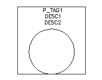
- Select the P_TAG1 attribute.
-
 Select the Properties tool to launch the Insert/Edit Attributes dialog box.
- Change the height to 0.125, Justify to Center, and Visible.
- Select OK.
-
 Click the Insert Attribute tool.
- Insert the attribute above the symbol graphics.
Note: You can also right-click and select Insert Attribute or drag the attribute to insert it.
-
 Select DESC1 and DESC2, click the Insert Attribute tool, and insert them below the P_TAG1. Use the Properties tool to change them to Height = 0.125, Justify = Center, and Visible.

- Insert the LOC, INST, MFG, CAT, and ASSYCODE attributes.
Note: If the CAT and ASSYCODE attributes are not listed they are inserted with MFG as a group.

Finishing the panel symbol
-
Click

 . Find
- Click Base Point: Pick point and select the insertion point for the graphics.
- Select Wblock. Wblock creates the symbol .dwg file, while Block creates the symbol for this drawing file only.
- Enter the Name and file path or keep the default. AutoCAD Electrical toolset provides a default name for the new symbol based on the attribute template selected.
- (Optional) If you are going to add the symbol to the icon menu at a later time using the Icon Menu Wizard, check Icon image. Enter the image name and folder.
- (Optional) Click Details to see the Symbol Audit dialog box listing potential issues with your symbol.
- Select OK.
- Select Close Block Editor from the block editor toolbar.
- (Optional) Select Yes to insert the symbol on the drawing and select a location.
Additional Options
The additional options for creating a symbol listed are not used for this example, but you can use them when creating your own symbol.
-
Optional Attributes: The attributes listed in this section are allowed on a panel footprint. You can also add attributes to the Required or Optional list using the following steps.
 Select the Add Attribute tool to launch the Insert/Edit Attributes dialog box.
- Enter the attribute name as the Tag value.
- Enter all property values.
- Click Insert to insert the attribute or OK to add it to the list without inserting it.
-
RATING section: You can add up to 12 Rating attributes. If the attribute template contains a RATING1 attribute, or you add one, this section is available on the Symbol Builder Attribute Editor.
- Expand the RATING section.
 Select the Add Next tool.
- Pick an insertion point.
-
Convert Text to Attribute dialog box: If you selected existing text entities from the Select Symbol/Objects dialog box, or added text while in the Block Editor environment, this option converts existing text entities to AutoCAD Electrical toolset attributes in the same location as the original text.
 Select the Convert Text to Attribute tool from the Symbol Builder toolbar to launch the dialog box.
- Select a text entry in the list and click the arrow pointing at the attribute name.
- Repeat for all text entities.
- Click Done. The text entity is converted to the attribute. The text value becomes the default value for the attribute.
-
Convert text: If you selected existing text entities from the Select Symbol/Objects dialog box, or added text while in the Block Editor environment, this option converts a single text entity to an AutoCAD Electrical toolset attribute in the same location as the original text.
- Select an attribute on the Symbol Builder Attribute Editor.
 Select the Convert Text tool.
- Select the text entity. The text entity is converted to the attribute. The text value becomes the default value for the attribute.
- Audit Symbol: At any time you can audit the symbol to find any potential issues with your symbol.
Adding attributes using templates
An alternative to using the Symbol Builder to add attributes to the panel footprint, is to use an attribute template to add attributes automatically. You can have certain attributes added to any footprint automatically at footprint insertion time. The templates are located in C:\Users\Public\Documents\Autodesk\Acade {version}\Libs\panel\.
You can set up to have visible attributes added to any footprint automatically at footprint insertion time. There are five attribute template drawings:
|
wd_ptag_addattr_comp.dwg |
component footprints |
|
wd_ptag_addattr_trm.dwg |
terminal with terminal number |
|
wd_ptag_addattr_wtrm.dwg |
terminal with wire number as terminal number |
|
wd_ptag_addattr_itemballoon.dwg |
balloons |
When a panel footprint is inserted, the following steps are performed if the appropriate attribute template exists.
- Find the center of the footprint by collecting and averaging the objects that make up the footprint.
- Insert the attribute template at the calculated center of the footprint.
- Make sure there are no duplicate attributes. If duplicate attributes are found, the attribute from the footprint is kept.
- Re-block the added attributes with the inserted footprint.
- Add the schematic data to the footprint. The data is added as attribute data if the target attribute exists. If the target attribute does not exist, the data is added as invisible xdata.