Select, insert, and annotate a PLC module.
AutoCAD Electrical toolset generates any of hundreds of different PLC I/O modules on demand. The modules generate in various different graphical styles, all without a single, complete I/O module library symbol resident on the system. Modules adapt to the underlying ladder rung spacing, whatever that value is. They can be stretched or broken into two or more pieces at insertion time.
To insert a PLC module, you select the module and pick a location. AutoCAD Electrical toolset builds and inserts the module, using a small set of library symbols.
Insert a PLC module
- If AEGS is not the active project, in the Project Manager, right-click AEGS and select Activate.
- In the Project Manager, double-click AEGS to expand the drawing list.
- In the Project Manager, Project Drawing List, double-click AEGS05.dwg.
- Click


 . Find
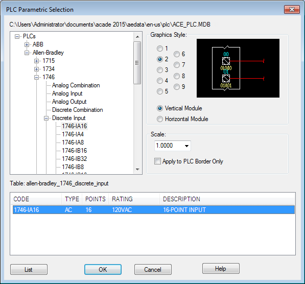
- In the PLC Parametric Selection dialog box, select:
Manufacturer: Allen-Bradley
Series: 1746
Type: Discrete Input
Part Number: 1746-IA16
Graphics Style: 2, Vertical Module

- Click OK.
- Respond to the prompts as follows:
Specify PLC module insertion point or [Z=zoom, P=pan]:
Pick a point on wire line reference 520 closer to the right side, ensure the X is near the horizontal wire, click

- In the Module Layout dialog box, verify the default settings:
Spacing: 1.0000
I/O Points: Insert all
Click OK.
AutoCAD Electrical toolset reads the vertical rung spacing of your ladder and calculates how long the module is going to be. It multiplies the rung spacing by the number of wire connections specified by the module you selected.
Temporary graphics display a representation of the module (with the spacing defined) to help position the module on the ladder.
- In the I/O Point dialog box, specify:
Rack Number: 1
Slot Number: 1
Note: Specify the values by either entering text into the edit boxes or by clicking the arrows. - Click OK.
- In the I/O Address dialog box, specify:
Beginning address: I:11/00
Note: You can also select the beginning address from the Quick picks list. - Click OK.
- In the I/O Addressing dialog box, click Decimal.
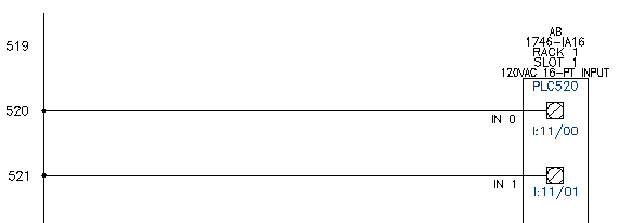
The PLC module is inserted into your drawing with incremental address numbers already annotated as the module goes in, it breaks and reconnects to underlying wires.

You can break an I/O module into as many pieces as you want at insertion time. It is great for high-density modules that do not fit into a single ladder column. Use the Allow spacers/breakers option in the Module Layout dialog box at insertion time to do it.
You can also add extra space between adjacent I/O points using the Stretch Block tool. This feature leaves extra room when you know ahead of time that a certain I/O point will have additional components wired tied to a single I/O point after a PLC module is inserted.
Note: It can be used on any block, not just a PLC module.
Remove ladder rungs
- Click

 . Find
- Respond to the prompts as follows:
Fence/Crossing/Zext/<Select wire to TRIM>:
Select the ladder rung at line reference 519, right-click
The ladder rung is removed from your drawing.
