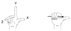
The User Coordinate System (UCS) is a movable coordinate system, which is a fundamental tool both for 2D drawing and 3D modeling.
- The XY plane, also called the work plane, on which objects are created and modified
- The horizontal and vertical directions used for features like Ortho mode, polar tracking, and object snap tracking
- The alignment and angle of the grid, hatch patterns, text, and dimension objects
- The origin and orientation for coordinate entry and absolute reference angles
- For 3D operations, the orientation of work planes, projection planes, and the Z axis for vertical direction and axis of rotation
You can change the location and orientation of the current UCS by clicking the UCS icon and using its grips, or with the UCS command. Display options for the UCS icon are available with the UCSICON command.
Understand the UCS in 3D
When you create or modify objects in a 3D environment, you can move and reorient the UCS anywhere in 3D space to simplify your work. The UCS is useful for entering coordinates, creating 3D objects on 2D work planes, and rotating objects in 3D.

The UCS in Paper Space
You can define a new UCS in paper space just as you can in model space; however, the UCS in paper space is restricted to 2D manipulation. Although you can enter 3D coordinates in paper space, you cannot use 3D viewing commands such as PLAN and VPOINT.
Understand the World Coordinate System (WCS)
The WCS is a fixed Cartesian coordinate system. Internally, all objects are defined by their WCS coordinates, and the WCS and the UCS are coincident in a new drawing. However, it is usually more convenient to create and edit objects based on the UCS, which can be customized to suit your needs.