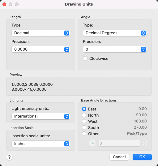
Controls the displayed precision and format for coordinates and angles.
UNITS (Command)
Menu: .

List of Options
The following options are displayed.
Length
Specifies the current unit of measurement and the precision for the current units.
- Type
-
Sets the current format for units of measure. The values include Architectural, Decimal, Engineering, Fractional, and Scientific. The Engineering and Architectural formats produce feet-and-inches displays and assume that each drawing unit represents one inch. The other formats can represent any real-world unit.
- Precision
-
Sets the number of decimal places or fractional size displayed for linear measurements.
Angle
Specifies the current angle format and the precision for the current angle display.
- Type
-
Sets the current angle format.
- Precision
-
Sets the precision for the current angle display.
The following conventions are used for the various angle measures: decimal degrees appear as decimal numbers, grads appear with a lowercase g suffix, and radians appear with a lowercase r suffix. The degrees/minutes/seconds format uses d for degrees, ' for minutes, and " for seconds; for example:
123d45'56.7"
Surveyor's units show angles as bearings, using N or S for north or south, degrees/minutes/seconds for how far east or west the angle is from direct north or south, and E or W for east or west; for example:
N 45d0'0" E
The angle is always less than 90 degrees and is displayed in the degrees/minutes/seconds format. If the angle is precisely north, south, east, or west, only the single letter representing the compass point is displayed.
- Clockwise
-
Calculates positive angles in the clockwise direction. The default direction for positive angles is counterclockwise.
When prompted for an angle, you can point in the desired direction or enter an angle regardless of the setting specified for Clockwise.
Preview
Displays an example of the current settings for units and angles.
Lighting
Controls the unit of measurement for the intensity of photometric lights in the current drawing. Photometric lights use the insertion scale to determine the units used in rendering, so Insertion Scale should be set to a unit style other than Unitless.
Insertion Scale
Controls the unit of measurement for blocks and drawings that are inserted into the current drawing. A block or a drawing that is created with units that are different from the units specified with this option is scaled when inserted. The insertion scale is the ratio of the units used in the source block or drawing and the units used in the target drawing. Select Unitless to insert the block without scaling it to match the specified units.
Base Angle Directions
Sets the direction of the zero angle. The following options affect the entry of angles, the display format, and the entry of polar, cylindrical, and spherical coordinates.
- East
-
Specifies the compass direction east (the default).
- North
-
Specifies the compass direction north.
- West
-
Specifies the compass direction west.
- South
-
Specifies the compass direction south.
- Other
-
Specifies a direction different from the points of the compass.
- Angle
-
Specifies a value for the zero angle when Other is selected.
- Pick an Angle Button
-
Defines the zero angle in the graphics area based on the angle of an imaginary line that connects any two points you specify with the pointing device.