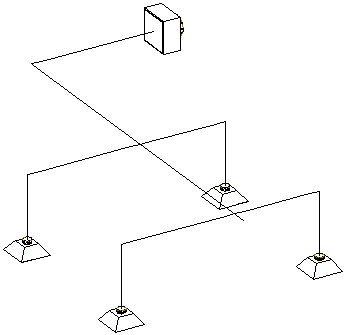
- Select any object in a connected system.

An example of a 1-line system.
- Click Duct Flex tab or

 .
.
- In the Duct Size Calculator, specify which ducts to size:
To... then... size all objects in a system select Calculate complete system. size selected objects select Calculate selected objects, click  , and select the objects you want to size. Press enter.
 - Specify the shape for the sized ducts:
To... then... specify the same shape for all parts select All and specify a shape. specify different shapes for the trunk and runouts select Individual. Specify a shape for Trunk and for Runouts. Note that there must be a fan at the start of the system to use the Inherit from Fan shape for Trunk. specify the runouts to use the same shape and size as the air terminal connection select Use shape and size from air terminals on runouts. Note that this deactivates Runout shape if you are specifying individual shapes for the trunk and runouts. Note: If you are sizing ducts with defined shapes, you cannot change their shape. You can calculate sizes, but you cannot override the shapes already assigned to the ducts. - Specify design parameters to apply to this calculation:
To... then... use different parameters than those specified in the HVAC System Definitions style select Override design parameters from system definition(s). Select the parameter (Velocity or Friction) to change, and enter a new value. These values are only used for this specific calculation. The system definition values remain the same, and are used on all subsequent calculations. specify a maximum diameter for round ducts select Round max. size and enter a value. If a duct must be larger than this diameter to meet flow requirements, specify Rectangular or Oval for For larger size. The height of the rectangular or oval duct will not exceed the maximum round size. specify a maximum height for rectangular or oval ducts select Rectangular/Oval Max. Height and enter a value. specify which duct sizes to use from the duct catalog select All, 1 inch increment, or Even sizes only. apply duct size calculations to any objects in the system that already have a defined shape select Apply sizing to parts with defined shape. - Click Start.
- When the calculations are complete, the system is resized in the drawing.

Example drawing converted to a sized 2-line duct system
If any errors occurred during calculations, click View Event Log for a description of the error.
Note: Duct segments are not broken into multiple segments. The calculated duct size is applied to the entire duct segment. For example, you may want to reduce the duct size at all points where the system services 2 air diffusers. To refine your system, you can break a duct into segments and recalculate sizes. For more information, see Breaking or Merging Duct Segments.