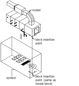
Generally, every part has a schematic symbol that you add to your schematic design layouts. Using Content Builder, you can assign each part a symbol block. You can assign a different symbol to each part size, or assign the same symbol to all part sizes. The symbol block provides a schematic representation of the part size for use in plan views. Typically, the same symbol block is used for all the part sizes in a part family. You must save the symbol block in an AutoCAD® drawing file. You can save one or more symbol blocks in the same drawing file.
You can use any drawing command to create the geometry for the blocks. Standard AutoCAD entities such as lines, polylines, or circles are recommended. Once the schematic symbol block is created, Content Builder scales and wraps the symbol block with a bounding box of the 3D model. This ensures that valid connections can be maintained between the schematic symbol and the connecting schematic lines.
To ensure correct display control of your symbol when it is added to your drawings, draw geometry for the symbol on layer 0, assign BYBLOCK for color and linetype, and assign BYLAYER for lineweight. The insertion point, or base point, is used as a reference for positioning the block upon insertion. The insertion point for the schematic block should be the same as the 3D model block that it represents. When you place the MvPart in a drawing, all associated blocks are part of one object; therefore, you want to maintain a common insertion point.

Content Builder wraps the schematic symbol with a bounding box of the 3D model and places the schematic symbol in the center of the bounding box. The bounding box is stretched around the extents of the 3D model in order to maintain accurate locations of the connection points. For easy identification, you should also use a standard naming convention that represents the part size or part family as you save your symbol block.