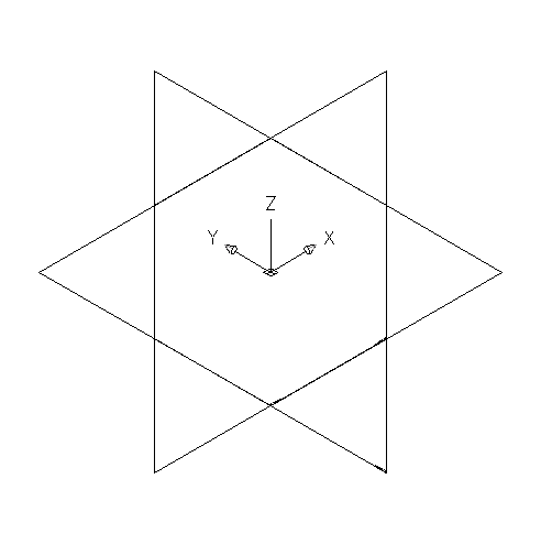
Work planes define the orientation in which you are working. They provide access to views, such as Front, Side, Top, etc., that let you create content.
Use this procedure to add work planes to create the geometry, paths, and constraints of a model. To avoid confusion, work with only one work plane visible, unless you are using offset or reference work planes. The following instructions refer to the part browser. The part browser is located under the ribbon to the left of the drawing area.
- In the part browser, expand Modeling.
- Right-click Work Planes and click Add Work Plane.
The Create Work Plane dialog box appears.
- Click Default, and click OK.
The ZX plane, YZ plane, and XY plane are created.
-
To view the work planes in the modeling area, on the floating View panel, click View drop-down

 .
.

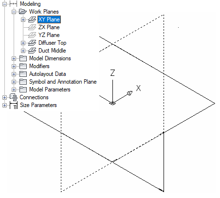
- In the part browser, expand Work Planes.
When you select a work plane in the part browser, the work plane is highlighted in the modeling area.

Selecting the ZX Plane
- To avoid confusion, work with only one work plane visible at a time. In the part browser, right-click ZX Plane and click Visible. Do the same for XY Plane.
The ZX Plane and XY Plane icons are unavailable (shaded). The YZ plane is the only visible work plane in the modeling area.